车门总成 - 充电接口(中国)(拆卸和更换)
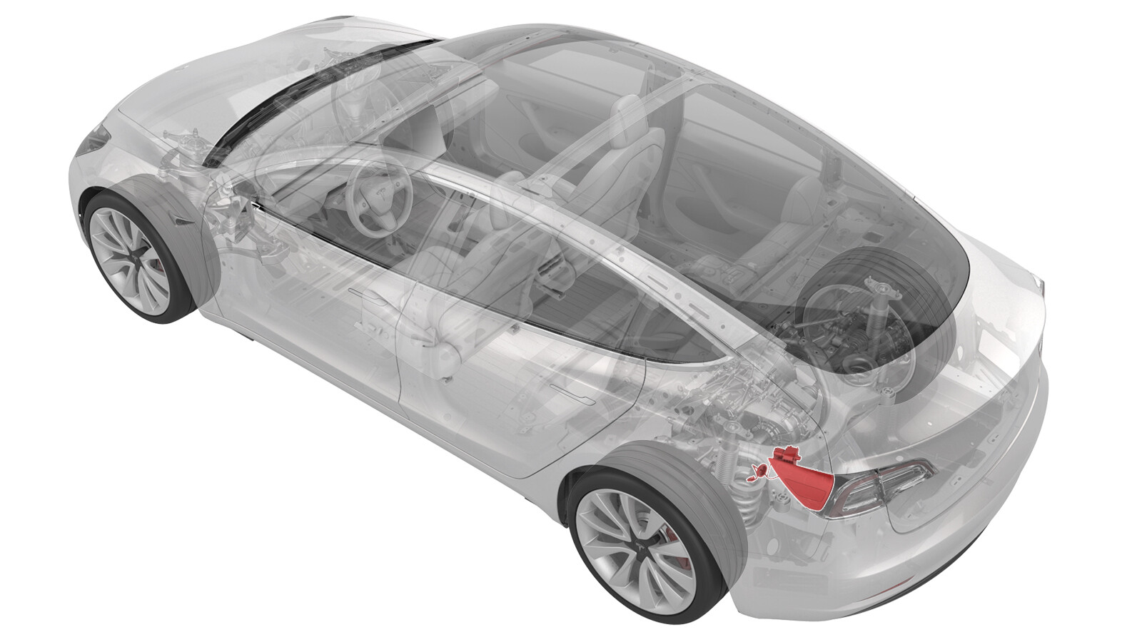 校正代码
44014302 0.66
NOTE: Unless otherwise explicitly
stated in the procedure, the correction code and its associated FRT reflect all of the
work required to perform this procedure, including the linked procedures. Do not stack correction codes unless
explicitly told to do so.
NOTE: See Flat Rate
Times to learn more about FRTs and how they are created.
NOTE: See 人员保护 to make sure wearing proper PPE when
performing the below procedure. NOTE: See 人体工程学注意事项 for safe and healthy working
practices.
- 2026-11-02: Added charge port connectors steps based on the latest validation.
- 2023-10-27: Update charge port to body bolt torque to 9 Nm.
- 2023-05-24: Removed the vehicle electrical isolation procedure.
Equipment:
- 1076921-01-B Insulation Multimeter, Fluke 1508
- 1130480-00-A Test Probes, Slim, Fluke TP38
Only
technicians who have completed all required certification courses are permitted to
perform this procedure. Tesla recommends third party service provider technicians
undergo equivalent training before performing this procedure. For more information on
Tesla Technician requirements, or descriptions of the subject matter for third parties,
see HV Certification Requirements. Proper personal protective equipment (PPE) and insulating HV
gloves with a minimum rating of class 0 (1000V) must
be worn at all times a high voltage cable, busbar, or fitting is handled. Refer to Tech Note TN-15-92-003, High Voltage Awareness
Care Points
for additional safety
information.
Remove all jewelry (watches, bracelets, rings, necklaces, earrings, ID tags, piercings, etc.) from your person, and all objects (keys, coins, pens, pencils, tools, fasteners, etc.) from your pockets before performing any procedure that exposes you to high voltage.
Proper personal protective equipment (PPE) is required to perform this procedure:
- High voltage insulating gloves
- Leather glove protectors
- High voltage glove tester
- Safety glasses
- Electrical hazard rated safety shoes
A glove inflator is the only recommended way to test HV gloves. Both HV gloves must pass testing before beginning this procedure. If either glove does not pass the air check, discard the pair.
Make sure that the HV gloves are not expired. HV gloves can be used up to 12 months after the testing date printed on the glove, but only 6 months after first use even if the gloves are still within the 12-month period.
拆卸
- Open all doors and lower all windows.
- Remove the rear underhood apron. See 前备箱挡板 - 后部(拆卸和更换).
- Open the trunk.
-
Apply masking tape around
the charge port area.
- Disconnect 12V power. See 12V/低压电源(断开和连接).
- Perform the charge port voltage check procedure. See 充电接口电压检查.
- Remove the trunk garnish. See 饰板 - 后备箱(拆卸和更换).
- Remove the trunk sill trim panel. See 饰板 - 门槛板 - 后备箱(拆卸和更换).
- Remove the trunk floor trim. See 饰板 - 底板 - 后备箱(拆卸和更换).
- Disconnect the LH liftgate task light connector.
- Release the edge of the trunk carpet, and then move the LH trunk side trim aside.
- Remove the LH taillight. See 尾灯 - 左侧(拆卸和更换).
-
Release the locking tab, and then
disconnect the electrical connector from the charge port assembly.
CAUTIONDO NOT push down on the red locking tab. Pull the tab away from the connector until the connector is unlocked, and then continue pulling the main body of the connector to fully disconnect it.
-
Remove the white locking tab, and then
disconnect the DC logic connector from the charge port.
-
Remove the white locking tab, and then
disconnect the AC logic connector from the charge port.
Figure 1. Model 3 shown, Model Y similar -
Push the locking tab upward, and then
disconnect the 3-phase connector from the charge port.
Figure 2. Model 3 shown, Model Y similar -
Use a pick to gently release the tabs
(x2) that attach the safety cap to the busbar brackets, and then remove the safety
cap.
NoteDo not pry with excessive force, as doing so could damage the safety cap.
- Put on High Voltage (HV) insulating gloves and leather glove protectors.
-
Remove the nuts (x2) that
attach the charge port busbar leads to the charge port assembly.
Tip推荐使用以下工具
- 10 毫米深套筒
- Remove High Voltage (HV) insulating gloves and leather glove protectors.
- Release the charge port manual release cable from the body clip.
-
Remove the bolts that attach
the charge port to the body, and then remove the charge port from the
vehicle.
Tip推荐使用以下工具
- 10 毫米深套筒
- 回旋头棘轮/回旋头扭矩扳手
-
Disconnect the Low Voltage (LV)
electrical connectors from the charge port ECU.
- Disconnect the charge port door harness from the charge port ECU.
-
Release the charge port door
grommet from the body.
-
Release the lower clips that
attach the charge port door assembly to the vehicle, then push the bottom of
the assembly out, and then remove the assembly from the vehicle.
NoteTo ease the removal of the charge port door assembly:
- Pull the assembly towards the rear of the vehicle.
- When the assembly reaches the rear of the quarter panel, pull the assembly to clear the actuator mechanism, and then pull the assembly out and away from the body.
NoteManipulation of the charge port door assembly might be necessary to completely remove the assembly from the body.
安装
-
Install the charge port door
assembly on the vehicle: Pivot the assembly so that the actuator mechanism
clears underneath the quarter panel, and then slide the assembly forward
towards the rear door.
NoteManipulation of the charge port door assembly might be necessary to fully align the assembly to the rear quarter,
-
Push the charge port door
assembly electrical harness through the opening, and then attach the charge
port door assembly with lower clips (x2).
-
Install the charge port door
grommet on the body.
WarningMake sure the harness is routed out, and the adhesive pad with zip tie is properly mounted if it is installed.
- Connect the charge port door harness from the charge port ECU.
- Put on High Voltage (HV) insulating gloves and leather glove protectors.
- Clean the charge port busbar HV header at the back of the charge port assembly with an IPA wipe, and then air dry for 1 minute.
-
Position the charge port in
the vehicle, and then install the nuts that attach the charge port to the
body.
 9 Nm (6.6 lbs-ft)Tip推荐使用以下工具
- 10 毫米深套筒
- 回旋头棘轮/回旋头扭矩扳手
-
Use the Hioki resistance meter to measure the resistance at the HV joint
between the HV busbar lead and charge port stud.
NoteThe acceptable resistance is between 0.050 mΩ (60 μΩ) and 0.325 mΩ (325 μΩ). Per the performance value, do the following:
- If the resistance is above 0.325 mΩ (325 μΩ), there is too much resistance in the High Voltage joint. Remove the fastener, clean areas with isopropyl alcohol, install fastener back and test again, as appropriate.
- If the resistance is lower than 0.050 mΩ (60 μΩ), reposition the probes and measure again.
- If the resistance is repeatedly between 0.00 mΩ and 0.050 mΩ (50 μΩ), proceed to the next step.
- Remove High Voltage (HV) insulating gloves and leather glove protectors.
-
Install the safety cap on the busbar
brackets, making sure to engage the two locking tabs.
-
Connect the 3-phase connector on the
charge port, and then slide the locking tab downward.
Figure 3. Model 3 shown, Model Y similar -
Connect the AC logic connector on the
charge port, and then install the white locking tab.
v
Figure 4. Model 3 shown, Model Y similar -
Connect the DC logic connector on the
charge port, and then install the white locking tab.
Figure 5. Model 3 shown, Model Y similar -
Connect the electrical connector to
the charge port actuator, and then engage the locking tab.
CAUTIONPush the red locking tab towards the connector to engage the locking mechanism. DO NOT push down or pull up on the red locking tab.
- Remove the old connector housing gasket and install a new one.
- If the taillight is to be reinstalled, replace the gaskets from around each taillight mounting bolt (x2) and the taillight electrical connector (x1).
- Position the LH taillight studs into the grommets, and then install the taillight onto the vehicle.
- Install the LH liftgate bump stop.
- Remove the masking tape from around the charge port area.
- Move the LH trunk side trim back into position.
- Connect the LH liftgate task light connector.
- Install the trunk garnish. See 饰板 - 后备箱(拆卸和更换).
- Install the trunk sill trim panel. See 饰板 - 门槛板 - 后备箱(拆卸和更换).
- Install the rear trunk load floor.
- Reconnect 12V power. See 12V/低压电源(断开和连接).
- Install the rear underhood apron. See 前备箱挡板 - 后部(拆卸和更换).
-
Verify the operation of the
charging system:
NoteUse the customer's charging equipment, if present.
- Raise all windows and close and all doors.