副车架总成 - 后(拆卸和安装)
 校正代码
30010201 2.22
NOTE: Unless otherwise explicitly
stated in the procedure, the correction code and its associated FRT reflect all of the
work required to perform this procedure, including the linked procedures. Do not stack correction codes unless
explicitly told to do so.
NOTE: See Flat Rate
Times to learn more about FRTs and how they are created.
NOTE: See 人员保护 to make sure wearing proper PPE when
performing the below procedure. NOTE: See 人体工程学注意事项 for safe and healthy working
practices.
- 2026-11-02: Updated torque specifications.
- 2026-01-29: Added photos to show how to position the subframe lifting tool.
- 2025-12-12: Updated torque table and torque values shown in the procedure.
- 2024-10-14: Updated torque spec for LH/RH shear plate-to-rear subframe large bolts.
Equipment:
- 1134520-00-A 电子驻车制动 (EPB) 手动释放套件
- 1129348-00-A XP-10 电源,XP-10
- 1099645-00-B 副车架固定装置,Model 3
- 1140311-00-A Lever Lock, HV Connector, Model 3
扭矩规格
| 描述 | 扭矩值 | 推荐工具 | 重复使用/更换 | 备注 |
|---|---|---|---|---|
| Bolts that attach the LH rear brake caliper bracket to the knuckle |
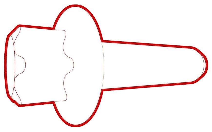 83 Nm (61.2 lbs-ft) |
|
更换 | |
| Bolts that attach the LH rear damper at the top mount |
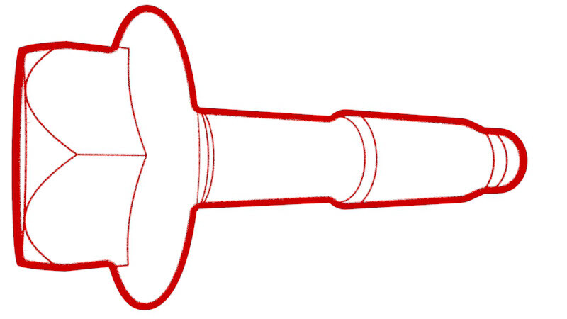 41 Nm (30.2 lbs-ft) |
|
重复使用 | |
| Nut that attaches the rear drive unit ground strap to the body |
 10 Nm (7.4 lbs-ft) |
|
重复使用 | |
| Nuts that attach the HV battery to rear drive unit harness bracket to the HV battery |
 10 Nm (7.4 lbs-ft) |
|
重复使用 | |
| Small bolts that attach the LH shear plate to the HV battery |
 35 Nm (25.8 lbs-ft) |
|
重复使用 | |
| Large bolt that attaches the LH shear plate and rear subframe to the body |
 125 Nm (92.2 lbs-ft) |
|
更换 | |
| Bolts that attach the rear subframe to the body |
 160 Nm (118.0 lbs-ft) |
|
更换 |
拆卸
- Raise and support the vehicle. See 举升车辆 - 双柱举升机.
- Open all doors and lower the windows.
- Release the parking brakes. See 驻车制动 - 钳 - 后 - 左侧(释放).
- Remove the 2nd row lower seat cushion. See 座椅座垫 - 下部 - 第二排(拆卸和更换).
- Remove the rear underhood apron. See 前备箱挡板 - 后部(拆卸和更换).
- Disconnect 12V power. See 12V/低压电源(断开和连接).
- Perform the vehicle electrical isolation procedure. See 车辆高压禁用程序.
- Remove the LH and RH rear wheels. See 轮毂(拆卸和安装).
- Remove the LH and RH suspension cover. See 护罩 - 后悬架 - 左侧(拆卸和更换).
- Remove the mid aero shield panel. See 面板 - 流线型护板 - 后部(拆卸和更换).
- Remove the rear fascia diffuser. See 扩散器 - 后饰板(拆卸和更换).
-
Remove the nut that attaches the rear
drive unit ground strap to the body.
Tip推荐使用以下工具
- 10 毫米 12 角深套筒
-
Remove and discard the bolt that
attaches the LH rear brake caliper bracket to the knuckle, and then hang the caliper
bracket on the body with an S-hook. Repeat this step on the RH rear brake caliper.
Tip推荐使用以下工具
- 外梅花套筒 E18
-
Install a spring compressor onto the
LH rear coil spring.
Tip推荐使用以下工具
- Gedore 弹簧压缩器
-
Remove the bolts (x2) that attach the
LH rear damper to the top mount.
Tip推荐使用以下工具
- 15 毫米套筒
- 3 英寸加长件
- Repeat steps 14 and 15 on the RH rear damper.
-
Disconnect the electrical harness from
the LH 12V subframe connectors.
-
Release the clip that attaches the LH
subframe electrical harness to the body.
- Repeat steps 17 and 18 on the RH side of the vehicle.
- Remove the rear stabilizer bar. See 平衡杆 - 后(拆卸和更换).
- Remove the rear HV battery skid plate. See 滑板 - 高压电池 - 后部(拆卸和更换).
- Position a coolant drain container under the LH rear of the HV battery.
-
Disconnect the rear drive unit
inverter inlet hose from the LH rear side of the HV battery, and then plug the male and
female fittings.
- Position the coolant drain under the RH rear of the vehicle.
- Release the push clips (x2) that attach the RH rear wheel liner to the rocker panel.
-
Release the clip, disconnect the rear
drive unit coolant outlet hose to powertrain return hose, and then plug the male and
female fittings.
- Remove the coolant drain container from under the vehicle.
-
Remove the nut that attaches the HV
battery to rear drive unit harness bracket to the HV battery.
NoteThe number of fasteners may vary.Tip推荐使用以下工具
- 10 毫米套筒扳手
- 4 英寸加长件
-
Slide the release to unlock the HV
battery rear drive unit connector handle of the rear drive unit to HV battery harness
from the secured position.
-
Fully raise the handle on the HV
battery rear drive unit connector, and then remove the HV battery rear drive unit
connector from the HV battery header.
-
Position the subframe lifting tool
under the rear subframe.
-
Attach an air hose to the subframe
lifting tool.
-
With an assistant, raise the subframe
lifting tool to support the rear subframe.
-
Loop the straps over the rear
subframe, hook the ends of the straps to the metal rings, and then pull the straps tight
to restrain the subframe to the rear subframe lifting tool.
NoteLower the vehicle to give more slack to connect the straps to the rings, if necessary.
-
Mark the LH and RH rear subframe bolts
for realignment during re installation.
NoteYou can also mark the LH and RH subframe casting and subframe bushing to the body.
-
Release the fir tree clips that attach
the coolant hoses to the LH shear plate.
-
Remove the smaller bolts that attach
the LH shear plate to the HV battery.
Tip推荐使用以下工具
- 13 mm 套筒
- 3 英寸加长件
-
Remove the larger bolt that attaches
the LH shear plate and rear subframe to the body, and then remove the LH shear
plate.
Tip推荐使用以下工具
- 21 毫米套筒
- 6 英寸加长件
- Repeat step 36 through step 38for the RH shear plate.
-
Remove and discard the bolts (x2) that
attach the rear subframe to the body.
Tip推荐使用以下工具
-
With an assistant, slowly lower the
subframe lifting tool to remove the rear subframe from the vehicle.
CAUTIONTake care not to damage HV harnesses and coolant hoses during lowering of the subframe.
- Disconnect the air supply from the rear subframe lifting tool.
-
Move the rear subframe and subframe
lifting tool away from the vehicle.
安装
- Position the subframe lifting tool and rear subframe underneath the vehicle.
- Connect the air line to the subframe lifting tool.
-
With an assistant, slowly raise the
rear drive unit and subframe into position.
CAUTIONTake care not to damage HV harnesses and coolant hoses while lifting the rear subframe.
-
Hand-tighten new bolts (x2) that
attach the rear subframe to the body.
NoteThe tightening of the bolts will be performed later in this procedure.
-
Install the LH shear plate to the rear
subframe and HV battery, and then hand-tighten a new bolt to attach the shear plate to
the subframe.
NoteThe tightening of the bolt will be performed later in this procedure.
-
Install and hand-tighten the smaller
bolts that attach the LH shear plate to the HV battery.
NoteThe tightening of the bolts will be performed later in this procedure.
- Repeat steps 5 and 6 on the RH shear plate.
-
Position the subframe to the locations
as marked during removal.
NoteReturn the subframe to its original position as closely as possible.
-
Torque the bolts that attach the LH
and RH rear subframe to the body, and then mark them with a paint pen after
torquing.
Tip推荐使用以下工具160 Nm (118.0 lbs-ft)
-
Torque the smaller bolts that attach
the LH and RH shear plates to the vehicle.35 Nm (25.8 lbs-ft)Tip推荐使用以下工具
- 13 mm 套筒
- 3 英寸加长件
-
Torque the large bolts that attach the
LH and RH shear plates to the vehicle, and then mark them with a paint pen after
torquing.125 Nm (92.2 lbs-ft)Tip推荐使用以下工具
- 21 毫米套筒
- 6 英寸加长件
-
Fasten the fir tree clips that attach
the coolant hoses to the LH and RH shear plates.
LH shear plate shown, RH shear plate similar
- Release the straps and lower the subframe lifting tool from the vehicle.
- Disconnect the air line from the subframe lifting tool, and then remove the tool from underneath the vehicle.
-
Fully raise the handle on the HV
battery rear drive unit connector of the rear drive unit to HV battery harness.
-
Install the HV connector special tool
onto the HV battery rear drive unit connector.
-
Use both hands to firmly connect the
HV battery rear drive unit connector of the rear drive unit to HV battery harness to the
HV battery header.
CAUTIONMake sure that the connector fits the header squarely and tightly, and that both retention pins enter the handle.
- Remove the HV connector special tool from the HV battery rear drive unit connector.
-
While pressing the HV battery rear
drive unit connector onto the HV battery header, fully lower the handle.
CAUTIONMake sure that the handle does not bind as it is lowered.
-
Slide the release to lock the HV
battery rear drive unit connector handle in the secured position.
-
Verify that the HV battery rear drive
unit connector is fully seated, and compare both sides of the connector that it is
properly secured in place.
NoteAn improperly seated connector might lead to connector damage and rear drive unit problems later on.
-
Install the nuts (x2) that attach the
rear drive unit HV electrical harness bracket to the HV battery.10 Nm (7.4 lbs-ft)Tip推荐使用以下工具
- 10 毫米套筒扳手
- 4 英寸加长件
NoteThe number of fasteners might vary on newer vehicles. - Position the coolant drain beneath the RH rear of the HV battery.
-
Remove the hose plugs, connect the
rear drive unit outlet hose to the powertrain return hose, and then fasten the
clip.
CAUTIONPerform a push-pull test to verify that the hose is fully seated.
- Position the coolant drain beneath the LH rear of the HV battery.
-
Remove the plugs from the male and
female fittings, connect the rear drive unit inverter inlet hose to the LH side of the
HV battery, and then fasten the clip.
CAUTIONPerform a push-pull test to verify that the hose is fully seated.
- Fasten the barrel clip that attaches the rear drive unit inverter inlet hose to the HV battery.
- Remove the coolant drain container from underneath the vehicle.
- Install the rear HV battery skid plate. See 滑板 - 高压电池 - 后部(拆卸和更换).
- Install the rear stabilizer bar. See 平衡杆 - 后(拆卸和更换).
-
Fasten the LH subframe electrical
harness barrel clip to the body.
-
Connect the electrical connector for
the LH of the 12V subframe harness.
Figure 1. LH side shown, RH similar - Repeat steps 31 and 32 on the RH side of the vehicle.
-
Install the ground strap for the rear
drive unit.10 Nm (7.4 lbs-ft)Tip推荐使用以下工具
- 10 毫米 12 角深套筒
NoteReinstall the washer if the vehicle had this washer during removal.NoteMake sure that the angle of the ground strap provides enough clearance between the ground strap wire and the ABS wheel speed sensor wiring harness. -
Install the bolts that attach the LH
rear damper at the top mount.41 Nm (30.2 lbs-ft)Tip推荐使用以下工具
- 15 毫米套筒
- 3 英寸加长件
LH shown; RH similar.
-
Remove the spring compressor from the
LH rear coil spring.
- Install the LH rear suspension cover. See 护罩 - 后悬架 - 左侧(拆卸和更换).
- Repeat steps 35 through 37 on the RH side of the vehicle.
-
Install the LH and RH rear brake
caliper bracket onto the knuckle, and then install the bolts that attach the caliper
bracket to the knuckle.83 Nm (61.2 lbs-ft)Tip推荐使用以下工具
- 外梅花套筒 E18
LH rear brake caliper shown, RH rear brake caliper similar.
- Check the torque for any rear suspension bolts that were loosened while the rear subframe assembly was removed from the vehicle and torque as required. See 悬架 - 后部(检查扭矩).
- Install the rear fascia diffuser. See 扩散器 - 后饰板(拆卸和更换).
- Install the lower clips that attach the LH and RH wheel arch liner.
- Install the mid aero shield panel. See 面板 - 流线型护板 - 后部(拆卸和更换).
- Install the LH and RH rear wheels. See 轮毂(拆卸和安装).
- Connect 12V power. See 12V/低压电源(断开和连接).
- Press and hold the Park button on the gear selector to release the EPB service mode.
-
通过“维护模式”或 Toolbox 执行以下例行程序(请参阅0005 - 维护模式):
TEST-SELF_VCFRONT_X_THERMAL-PERFORMANCEvia Service Mode:Thermal ➜ Actions ➜ Test Thermal Performancevia Service Mode Plus:
- Drive Inverter ➜ Front Drive Inverter Replacement ➜ Thermal System Test
- Drive Inverter ➜ Rear Drive Inverter Replacement ➜ Thermal System Test
- Drive Inverter ➜ Rear Left Drive Inverter Replacement ➜ Thermal System Test
- Drive Inverter ➜ Rear Right Drive Inverter Replacement ➜ Thermal System Test
- Drive Unit ➜ Front Drive Unit Replacement ➜ Thermal System Test
- Drive Unit ➜ Rear Drive Unit Replacement ➜ Thermal System Test
-
Inspect the coolant level and top off
as necessary, and then install the coolant bottle cap.
NoteEnsure that the coolant level is at the "MAX" line.
- Install the cabin intake duct. See 槽 - 上部 - 驾驶室进气(拆卸和更换).
- Install the rear underhood apron. See 前备箱挡板 - 后部(拆卸和更换).
- Install the 2nd row lower seat cushion. See 座椅座垫 - 下部 - 第二排(拆卸和更换).
- Restore the driver and front passenger seats back to their original position.
- Refer to the Alignment Requirement tables to determine whether an EPAS alignment check (EC) or four wheel alignment check (AC) is necessary. If performed, add the alignment check/adjust correction code as a separate activity to the SV. See 定位要求 - 悬架.