17/06/2024 21:24:30

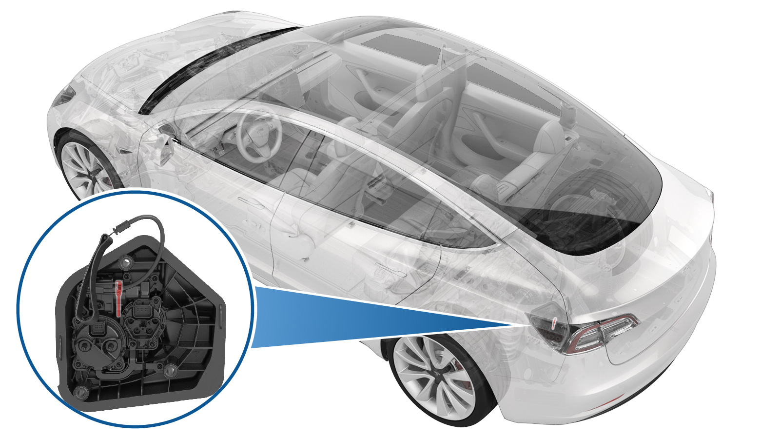
闩锁销 - 直流 - 充电接口(中国)(拆卸和更换)

校正代码 44011142 0.60 注意:除非本程序中另有明确规定,否则上述校正代码和 FRT 反映的是执行本程序(包括关联程序)所需的所有工作。除非明确要求,否则请勿堆叠校正代码。注意:请参阅平均维修工时,深入了解 FRT 及其创建方式。要提供有关 FRT 值的反馈,请发送电子邮件至LaborTimeFeedback@tesla.com注意:请参阅人员保护,确保在执行以下程序时穿戴适当的个人防护装备 (PPE)。

Warning IconA warning icon, calling your attention to a possibly risky situation
警告
尽管此程序已经过验证,但仍是一个草案。可能没有警告和注意事项。请遵守安全要求,处理或靠近高压系统和部件时,请谨慎操作。请将校正修理内容及反馈发送至ServiceDevelopment@teslamotors.com
  1. Open all four doors.
    Informational PurposesAn informational icon, calling your attention
    If vehicle is being powered down, Latch rear doors to prevent accidental closure.
  2. Lower all four windows.
  3. Open liftgate from exterior switch.
  4. Open charge port door.
  5. Open hood.
    Informational PurposesAn informational icon, calling your attention
    Press "Open" button on touchscreen to release latch, Lift lid manually.
  6. Remove rear apron.
    Informational PurposesAn informational icon, calling your attention
    12x clips, Only store rear apron visible face upwards
  7. Power off vehicle from center display.
    Informational PurposesAn informational icon, calling your attention
    Via Controls > Safety > Power Off, Select Power Off button at warning dialogue box.
  8. Disconnect LV battery and First Responder Loop.
    Informational PurposesAn informational icon, calling your attention
    2x connectors, Lift up and release green locking tab, Pull black connector lock outwards to release connection, Release red lock tab on FRL, Allow 2 minutes for all electrical circuits to fully discharge.
  9. Remove all items from pockets and ensure not wearing metal items.
  10. Inspect HV insulating gloves.
    Informational PurposesAn informational icon, calling your attention
    确保高压绝缘手套未过期。有关某个地区的手套有效期信息,请参考TN-15-92-003
  11. Put on HV insulating gloves and leather over gloves.
    Informational PurposesAn informational icon, calling your attention
    Make sure to wear Electrical Protective Gloves any time Hioki tester is used.
  12. Verify there is no high voltage present at the charge port on the type 2 (AC charge inlet).
    Informational PurposesAn informational icon, calling your attention
    Make sure to wear PPE (HV gloves, safety glasses) when working on high voltage component, Be sure to place the positive test lead on the side of the HV pin just past the plastic protective covers Measure the the voltage between B+ (the four dead front pins) to B- (rear left door striker as a ground for the isolation check), If voltage is greater than 10V, pack contactors are not open or welded, Stop work and reach out to Service Engineering.
  13. Verify there is no high voltage present at the charge port on the Combo 2 (DC charge inlet).
    Informational PurposesAn informational icon, calling your attention
    Make sure to wear PPE (HV gloves, safety glasses) when working on high voltage component, Be sure to place the positive test lead on the side of the HV pin just past the plastic protective covers Measure the voltage between B+ (the two dead front pins) to B- (rear left door striker as a ground for the isolation check), If voltage is greater than 10V, pack contactors are not open or welded, Stop work and reach out to Service Engineering.
  14. Remove HV insulating gloves.
  15. Remove clips securing upper trunk garnish to body.
    Informational PurposesAn informational icon, calling your attention
    2x push clips
  16. Release upper trunk garnish from body.
    Informational PurposesAn informational icon, calling your attention
    6x clips
  17. Remove load floor.
    Informational PurposesAn informational icon, calling your attention
    Use pull tab located at rear edge of panel.
  18. Remove trunk sill trim assembly.
    Informational PurposesAn informational icon, calling your attention
    4x clips, Pull corner upward release clip on the end the away from body for remaining clips.
  19. Remove clips for LH trunk side trim.
    Informational PurposesAn informational icon, calling your attention
    5x push clips, The number of clips on newer vehicles may vary.
  20. Disconnect LH liftgate task light connector.
    Informational PurposesAn informational icon, calling your attention
    1x connector
  21. Release edge of trunk carpet and move LH trunk side trim aside.
    Informational PurposesAn informational icon, calling your attention
    2x clips, Partially release rear trunk carpet, Move LH trunk side trimaside and tuckcarpet under trim, Take care not to cause excessive creasing.
  22. Release logic connector from chargeport assembly.
    Informational PurposesAn informational icon, calling your attention
    1x connector, Remove white locking tab before disconnecting.
  23. Release AC 3 phase connector from chargeport assembly.
    Informational PurposesAn informational icon, calling your attention
    1x connector, Release locking tab upward.
  24. Remove charge port safety cap.
    Informational PurposesAn informational icon, calling your attention
    2x tabs, Gently release tabs to avoid damage, Do not apply excess force.
  25. Remove charge port busbar leads from charge port assembly.
    Informational PurposesAn informational icon, calling your attention
    2x nuts, 10mm, 9 Nm, Nuts have captured washers
  26. Release charge port manual release cable from body clip.
  27. Disconnect actuator connector.
    Informational PurposesAn informational icon, calling your attention
    1x connector, Do not push down on red tab, Pull red tab to disengage lock, Pull again to release connector
  28. Remove charge port assembly.
    Informational PurposesAn informational icon, calling your attention
    3x bolts, 10mm, 5.5 Nm
  29. Pull and hold the manual release cable to release the actuator.
  30. Remove actuator screws from charge port assembly.
    Informational PurposesAn informational icon, calling your attention
    2x screws, T20, 3.3 Nm, Newer vehicle is equipped with T20 tamper proo
  31. Remove actuator from charge port assembly.
    Informational PurposesAn informational icon, calling your attention
    Turn over 30 degrees and take out the actuator
  32. Remove DC charge port latch stick o-ring from charge port assembly.
    Informational PurposesAn informational icon, calling your attention
    1x o-ring, Discard after removal
  33. Remove DC charge port latch stick from actuator.
    Informational PurposesAn informational icon, calling your attention
    Rotate to release
  34. Lubricate DC latch stick and o-ring.
    Informational PurposesAn informational icon, calling your attention
    1x o-ring, Apply efficient amount of lubricant to latch stick and o-ring
  35. Install DC latch stick to actuator.
    Informational PurposesAn informational icon, calling your attention
    Rotate to install
  36. Install DC latch stick o-ring to charge port assembly.
    Informational PurposesAn informational icon, calling your attention
    Do not damage o-ring
  37. Position actuator to charge port assembly.
    Informational PurposesAn informational icon, calling your attention
    Gently push actuator, Make sure there is no gap between actuator and charge port
  38. Install screws securing actuator to charge port assembly.
    Informational PurposesAn informational icon, calling your attention
    2x screws, T20, 3.3 Nm, Newer vehicle is equipped with T20 tamper proo
  39. Inspect HV insulating gloves.
    Informational PurposesAn informational icon, calling your attention
    确保高压绝缘手套未过期。有关某个地区的手套有效期信息,请参考TN-15-92-003
  40. Put on HV insulating gloves and leather over gloves.
    Informational PurposesAn informational icon, calling your attention
    Make sure to wear Electrical Protective Gloves any time Hioki tester is used.
  41. Install charge port assembly.
    Informational PurposesAn informational icon, calling your attention
    3x bolts, 10mm, 5.5 Nm
  42. Connect actuator connector.
    Informational PurposesAn informational icon, calling your attention
    1x connector, Engage locking tab
  43. Secure charge port manual release cable onto body clip.
  44. Install charge port busbar leads to charge port assembly.
    Informational PurposesAn informational icon, calling your attention
    2x nuts, 10mm, 9 Nm, Nuts have captured washers, If excessive force is required to seat busbars, they may have been bent. Inspect for damage and replace if necessary
  45. Perform Hioki resistance test at each HV joint from HV busbar lead to charge port stud.
    Informational PurposesAn informational icon, calling your attention
    2x HV joints, The acceptable resistance is between 0.050 mΩ (50 μΩ) and 0.270 mΩ (270 μΩ).If the resistance is greater than 0.270 mΩ (270 μΩ), there is too much resistance in the High Voltage joint. Remove the fastener, clean areas with isopropyl alcohol, install fastener back and test again.If the resistance is lower than 0.050 mΩ (50 μΩ), reposition the probes and measure again.If the resistance is repeatedly between 0.00 mΩ and 0.050 mΩ (50 μΩ), Hioki test passed, proceed to next step.
  46. Install charge port safety cap.
    Informational PurposesAn informational icon, calling your attention
    2x tabs
  47. Install AC 3 phase connector to charge port assembly.
    Informational PurposesAn informational icon, calling your attention
    1x connector, Slide downward to engage
  48. Install logic connector to charge port assembly.
    Informational PurposesAn informational icon, calling your attention
    1x connector, 1x white locking tab
  49. Remove HV insulating gloves.
  50. Move LH trunk side trim back into position.
    Informational PurposesAn informational icon, calling your attention
    2x clips, Move LH trunk side trim back to original position, Secure clip onto body
  51. Connect LH liftgate task light connector.
    Informational PurposesAn informational icon, calling your attention
    1x connector
  52. Install clips for LH trunk side trim.
    Informational PurposesAn informational icon, calling your attention
    5x push clips, The number of clips on newer vehicles may vary
  53. Install trunk sill trim assembly.
    Informational PurposesAn informational icon, calling your attention
    4x clips, Align the latch with center slot then 2 locator to their slot and then press to secure the clips, Adjust the seal to overlap the trim
  54. Install load floor.
  55. Install trunk garnish onto body.
    Informational PurposesAn informational icon, calling your attention
    6x clips, Number of clips may vary on newer vehicles, Verify trunk seal is fully seated along garnish
  56. Install clips securing trunk garnish to body.
    Informational PurposesAn informational icon, calling your attention
    2x push clips
  57. Connect First Responder Loop and LV battery.
    Informational PurposesAn informational icon, calling your attention
    2x connectors, Secure FRL first, Seat LV battery connection and push black connector lock inwards to secure, Engage green locking tab when fully seated
  58. Install rear apron.
    Informational PurposesAn informational icon, calling your attention
    12x clips
  59. Close hood.
  60. Raise all windows.
  61. Close all four doors.
    Informational PurposesAn informational icon, calling your attention
    Unlatch rear doors before closing
  62. Close trunk.
  63. Verify operation of charging system.
    Informational PurposesAn informational icon, calling your attention
    Use customer's charging equipment if available, lightly push on the lower corner of CP door, once opening is confirmed then close the door, press the button on the charge handle, there can be brief time out once CP door is open confirm vehicle is charging by connecting charge handle to the vehicle, disconnect charge handle and confirm CP door closes, ensure all charging adapters are present
  64. Close charge port door.
    Informational PurposesAn informational icon, calling your attention
    Do not manually push to close the charging port door.