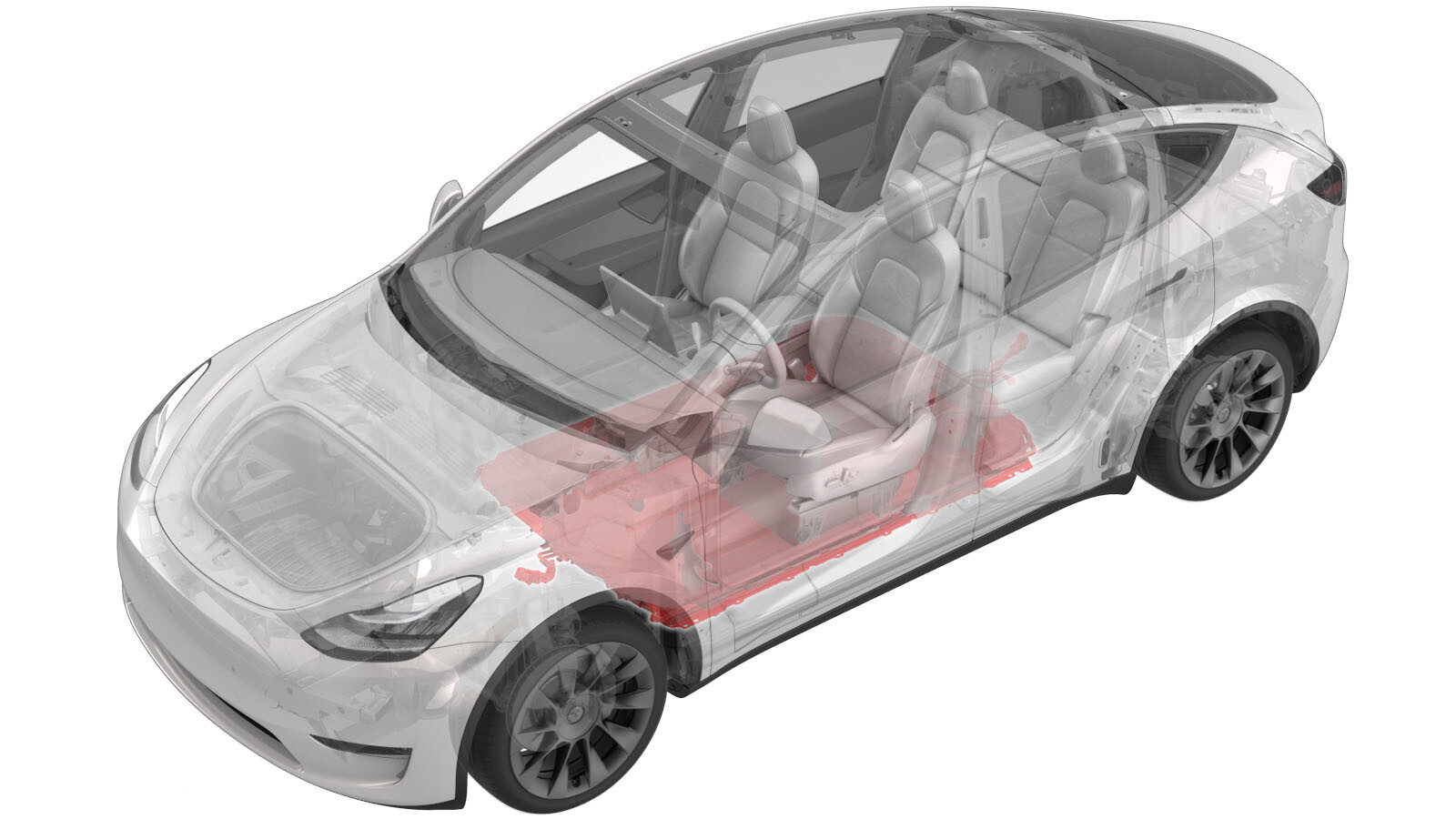
高压电池(全轮驱动)(结构化电池组)(拆卸和更换)
 校正代码
16010212 6.05
注意:除非本程序中另有明确规定,否则上文所列校正代码及相关 FRT 反映的是执行本程序(包括关联程序)所需的所有工作。除非明确要求,否则请勿堆叠校正代码。
注意:请参阅平均维修工时,深入了解 FRT 及其创建方式。
注意:请参阅人员保护,确保在执行以下程序时穿戴适当的个人防护装备 (PPE)。注意:请参阅人体工程学注意事项查看安全健康的作业规程。
- 2026-08-20: Moved steps for installation of lift adapters.
- 2026-05-28: Add a note of pack visual inspection before installation.
- 2026-05-20: Added warnings to never move the gantry with a suspended load or put any part of the body underneath a suspended load. Changed wording to clarify that crates are positioned under gantries rather than gantries moved over crates.
- 2025-10-10: Changed procedure sequence for cleaning the HV busbar and HV header connector contact surfaces.
- 2025-04-08: Added step for pyrotechnic battery disconnect when shipping the HV battery.
- 2024-12-18: Added step to determine if HV battery parameters are within safe limits before removing the pyro disconnect.
- 2024-11-07: Added 3-phase harness disconnect/connect steps.
- 2024-10-31: Updated HV battery discharge steps.
- 2024-09-11: Added step to support the LV system.
- 2024-06-13: Updated lift pad adapter PNs.
- 2024-06-07: Added pyro disconnect removal steps.
- 2024-02-13: Added information on thread repair on Front and Rear Under Body castings.
- 2023-11-21: Added new lift pad instructions.
- 2023-11-07: Updated UI steps and added references to wade seal procedures.
- 2023-08-25: Updated EPB Service Mode reference.
- 2023-05-22: Added conspicuous discharge warning table.
- 2023-04-13: Added notes and cautions for when the replacement HV battery is shipped on a plastic pallet and added steps to clean and check the wade seal fitment.
- 2023-03-16: Updated Discharge section and added steps to configure the HV battery.
- 2023-03-15: Simplified procedure with references.
只有完成全部所需认证的技术人员才能执行此程序。Tesla 特斯拉建议第三方服务提供商技术人员在执行此程序之前接受同等培训。有关 Tesla 技术人员要求的更多信息,或第三方主题说明,请参阅高压认证要求。处理高压线缆、母排或接头时,务必全程穿戴最低防护等级为 0(1000V) 的适当个人防护装备 (PPE)及高压绝缘手套。有关其他安全信息,请参阅技术注意事项 TN-15-92-003,高压安全意识注意事项
。
Discharge
|
警告:为遵从当地法律规定,高压锂电池必须在放电后打包运输。此外,高压电池也必须在放电后进行存放。要进行运输的高压电池,其充电状态 (SoC) 必须小于 25% 或 45%(以地区规定为准)。如果运输方式未知或不确定,或者电池需要存放,则建议将高压电池放电至 25% 以下。
警告:放电后,等待 20 分钟,确认充电状态低于目标值。等待 20 分钟后,开路电压 (OCV) 会稳定下来,这对于确保测量准确至关重要。如果充电状态未达到规定水平,请继续放电。 请确保使用高压电池通信工具收集所有高压电池装运数据,且最好是在将高压电池从车辆上拆下之前收集。 警告:切勿运输或存放已失去高压绝缘的高压电池。请先验证高压电池绝缘状况,再打包运输或进行存放。请参阅 Toolbox 文章#41977或客户文档CD-21-16-003中所述的高压电池通信工具,以确定高压电池参数是否处于运输或存放的安全限值范围内。 |
- Enable Service Mode Plus. See 维护模式增强版.
-
Identify the vehicle's current SOC Max: In the Service Mode Plus menu, touch , and then touch the large HV battery diagram to display the HV Battery information window.
- If the SOC Max is less than the SOC shipping threshold, skip to step 6 of this sub-procedure.
- If the SOC Max is greater than the SOC shipping threshold, continue to the next step.
- Move the vehicle to a location where the battery can be safely discharged unattended.
-
In the Service Mode Plus menu, touch .
-
In the Tools section, touch Start HV Discharge, and then in the window that opens, touch Run.
NoteThe discharge routine starts and will automatically stop when the SOC Max value for surface transport has been attained.
- After discharge is complete, use the HV Battery Communication Tool to collect HV battery shipping data, and then move the vehicle to the service bay.
拆卸
- Open all doors and lower the windows.
- Verify that the vehicle software version is at 2023.20 or later, and if not, update to the latest version. See 软件更新.
- Remove the LH and RH rocker panel carriers. See 支架 - 门槛板 - LH(结构化电池组)(拆卸和更换).
-
Remove the butyl patches (x4) that
cover the LH and RH rocker access holes.
- Enable the EPB Service Mode. See 驻车制动 - 钳 - 后 - 左侧(释放)
- If not already enabled, enable Service Mode Plus. See 维护模式增强版
-
Access the thermal system routines on the touchscreen: Touch Quick Controls > Service Mode > Diagnostics > Thermal.
NoteAuthorize routines by holding the turn signal stalk full up (right hand turn) while applying brake with the key in the vehicle.
-
Touch Start Thermal Fill Drain (Coolant Only) on the touchscreen.
NoteTouch the X at the top left of window to close once completed.NoteVerify the indicator displays green and the vehicle is ready for the coolant fill/drain.NoteThermal "Fill Drain" routine has a 5 hour time limit. After 5 hours, the routine must be performed again.
-
Disconnect and remove the laptop from the vehicle.
NoteDo not close Toolbox 3.0, we will need to resume later.
- Remove the LH and RH front seats. See 座椅总成 - 第一排 - 左侧(拆卸和更换).
- Remove the LH front carpet. See 地毯 - 前 - LH(结构化电池组)(拆卸和更换).
- Remove the LH carpet support. See 支架- 地毯 - LH(结构化电池组)(拆卸和更换).
- Remove the RH front carpet. See 毡毯 - 前 - RH(结构化电池组)(拆卸和更换).
- Remove the RH carpet support. See 支架 - 地毯 - RH(结构化电池组)(拆卸和更换).
- Remove the center console. See 中控台 (2.0)(结构化电池组)(拆卸和安装).
- Remove the 2nd row lower seat cushion. See 座椅座垫 - 下部 - 第二排(拆卸和更换).
- Remove the LH and RH lower C-pillar trim. See 饰板 - C 柱 - 下 - 左侧(拆卸和更换).
- Remove the LH and RH lower B-pillar trim. See 饰板 - B 柱 - 下 - LH(结构化电池组)(拆卸和更换).
- Remove the rear floormat.
-
Remove the clips (x3) that attach the rear main cabin carpet to the vehicle.
-
Remove the rear main cabin carpet from vehicle.
NotePull up at the rear of rear main carpet and slide back, then remove it from the LH rear door.
-
Remove the LH riser side carpet support bracket.
Note2x tabs.
-
Remove the RH riser side carpet support bracket.
Note2x tabs.
-
Remove the clip that attaches the center console harness to the body.
-
Remove the bolts (x4) that attach the LH and RH lower IP carrier brackets.
-
Remove the LH and RH floor ducts.
-
Remove and discard the bolts (x4) that attach the LH and RH center console lower rails.
NoteSlide the rails forward to disengage it from the center console riser assembly.
-
Loosen the rear inner HV battery bolts (x4) with a ratchet and remove them with a battery powered drill.
NoteBolts are located below the rear main carpet, bolt position 35 to 38.
-
安装举升垫适配器。
- 仅适用于欧洲、中东和非洲:安装举升机垫适配器,Model Y (1614078-00-A)
- 其他地区:安装通用举升垫适配器 (1936724-00-A)。
Warning请勿使用任何其他举升垫适配器。Note欧洲、中东和非洲以外地区:使用通用举升垫适配器 (1936724-00-A) 代替 举升机垫适配器,Model Y (1614078-00-A)。请弃用任何其他版本的举升垫适配器。Note通用举升垫适配器在欧洲、中东和非洲尚不可用。请确保在 Model Y 上使用 Model Y 橡胶举升垫,在 Model 3 上使用 Model 3 举升垫。通用举升垫适配器说明:
- Raise vehicle to a comfortable working height. See 举升车辆 - 双柱举升机.
- Remove the front aero shield. See 面板 - 流线型护板 - 前部(结构化电池组)(拆卸和更换).
- Remove the LH and RH front wheel arch liners. See 轮拱内衬 - 前 - LH(结构化电池组)(拆卸和更换)
- Remove mid aero shield. See 面板 - 流线型护板 - 后部(拆卸和更换).
- 执行车辆高压禁用程序。请参阅 车辆高压禁用程序 (结构化电池组)。
-
Remove the pyro disconnect from the ancillary bay prior to shipping the HV battery:
-
Disconnect the logic connector at the LH seat frame.
-
Remove the clip that attaches the logic connector harness to the LH seat frame.
-
Remove the bolt that attaches the busbar cover access door.
-
Remove the bolts (x2) that attach the charge port busbar kit to the HV header.
-
Disengage the clip that attaches the LH body harness to the rear body and move the harness aside.
-
Lift the busbar kit connector to remove it from the HV header.
NoteUse an inflatable air bag to suspend the busbar away from the HV header during removal and installation.
-
如果充电接口和高压电池之间有一个三相(交流)连接点,请将其断开:
-
Disconnect the HVC logic connector and install the logic cap.
-
Disconnect the LV power connector to HV battery.
- Raise the vehicle to a comfortable working height. See 举升车辆 - 双柱举升机.
-
Position a coolant drain container underneath the LH front of the HV battery.
-
Disconnect the PT supply hose at the LH front side of the vehicle.
Note1x spring clip. Plug hose connections as needed.
-
Install PCS flush adapter onto the PT supply hose.
NoteRemove plugs as needed. Perform push-pull-push test to confirm flush adapter is fully seated.
-
Attach coolant cart flush hose to regulator and PCS flush adapter.
NoteMake sure that the regulator valve is closed. The pressure regulator is not adjustable.
-
Position the coolant drain container underneath the LH RDU area.
-
Remove the clip that attaches the RDU inverter inlet hose to the RDU HV cable.
-
Disconnect the RDU inverter inlet hose from the fluid coupling.
NotePlug drive unit coupling.
-
Attach a compressed air line to the coolant pressure tester.
NoteMake sure that the valve on the pressure regulator is closed.
-
Slowly open the valve on the pressure regulator and allow coolant to completely drain.
NoteKeep an eye on all hose connections to make sure there are no leaks.
-
Close the valve on the pressure regulator when no more coolant is draining from the RDU inverter inlet hose.
-
Disconnect the compressed air line from the coolant pressure tester.
- Position the coolant drain container underneath the LH front of the HV battery.
-
Remove the PCS flush adapter from the PT supply hose.
NotePlug hose connections as needed.
-
Remove the PT flush fitting adapter from the cart pressure hose.
-
Position the coolant drain container underneath the center front of the HV battery pack.
NoteUnderneath the front left manifold battery supply tube.
-
Disconnect the front left manifold battery supply tube.
NotePlug hose connections as needed.
-
Attach the battery drain fitting adapter onto the front left manifold battery supply tube.
NoteMake sure the valve is closed and the adapter is locked to the manifold tube.
-
Secure the coolant cart flush hose to the battery drain fitting adapter.
-
Position the coolant drain container underneath the RH front of HV battery.
-
Disconnect the HV battery RH front inlet hose.
NotePlug the hose connections as needed.
-
Remove the clip that attaches the HV battery RH front inlet hose to the skid plate.
-
Attach the compressed air line to the coolant pressure tester.
NoteMake sure that the valve on the pressure regulator is closed.
-
Open the valve on the battery drain fitting adapter.
-
Slowly open the valve on the pressure regulator and allow coolant to completely drain.
NoteKeep an eye on all hose connections to make sure there are no leaks.
-
Close the valve on the pressure regulator when no longer coolant drains from the HV battery RH front inlet port.
-
Disconnect the compressed air from the coolant pressure tester.
-
Position the coolant drain container underneath the center front of the HV battery pack.
NoteUnderneath front left manifold battery supply tube.
-
Remove the battery drain fitting adapter from the front left manifold battery supply tube.
NotePlug hose connections as needed.
-
Remove the battery drain fitting adapter from the cart drain hose.
-
Position the coolant drain container underneath the RH front of the HV battery.
-
Disconnect the PT return hose at the RH front side of vehicle.
NotePlug hose connections as needed.
-
Remove the clip that attaches the PT return hose to the RH front side of the HV battery pack.
-
Remove the coolant drain container from underneath the vehicle.
-
Remove the bolt that attaches the FDU HV harness to the FDU.
-
Disconnect the FDU HV harness connector.
NoteRelease locking tab and rotate the release lever up to disengage the connector. Do not force the release lever up. Make sure that the alignment tabs on the FDU header are not damaged.
-
Remove the FDU HV harness connector from the FDU and move it aside.
-
Release the clip that attaches the PT coolant hose to the LH side of the front HV battery bash plate.
-
Release the compressor HV harness connection from the HV battery.
NoteHold down the red locking tab and disengage the release lever. Do not force the release lever up.
-
Release the clips (x4) that attach compressor HV harness to the rear of HV battery.
- Position the coolant drain container underneath the LH rear of the HV battery.
-
Remove the RDU inverter inlet hose.
NoteRotate the hose between the subframe and battery out of the vehicle.
-
Release the clips that attach the RDU oil cooler outlet pipe.
Note2x spring clips, 5x clips. Plug hose connections as needed.
-
Remove the RDU oil cooler outlet pipe.
NoteRotate it down over the RDU and rearward around the subframe.
- Remove the coolant drain container from underneath vehicle.
-
Remove the bolt that attaches the RDU HV cable bracket to the RDU.
-
Disconnect the RDU HV cable connector from the RDU.
NoteRelease the locking tab and rotate the release lever up to disengage the connector. Do not force the release lever up.
-
Remove the RDU HV cable.
NoteRotate the cable underneath the logic cable harness between the subframe and the HV battery.
-
Remove the smaller bolts (x4) for the LH and RH shear plates.
NoteBolt position 8-9 and 14-15.
-
Loosen the large bolt that attaches the LH shear plate and subframe to body and rotate the shear plate clear of the HV battery.
NoteHand tighten bolt once the shear plate is in position.
-
Loosen the large bolt that attaches the RH shear plate and subframe to the body and rotate the shear plate clear of the HV battery.
NoteHand tighten the bolt once the shear plate is in position.
-
Put a battery table into position and lower the vehicle to support the battery.
NoteRecommend assistance. Line up the table so the bolts at front bash plate are accessible and rear HV cables are accessible. Adjust final battery table position using adjustable caster jacks on the table.
-
Loosen the front bolts (x6) that attach the HV battery through the skid plate cover with a ratchet, and then remove them with a battery powered drill.
NoteBolt location 23 to 28.
-
Loosen the bolts (x6) that attach the skid plate to the vehicle with a ratchet, and then remove them with a battery powered drill.
NoteBolt location 29-34.
-
Loosen the bolts (x4) that attach the rear of the HV battery to the vehicle with a ratchet, and then remove them with a battery powered drill.
NoteBolt position 10-13.
-
Loosen the LH bolts (x7) that attach the HV battery to the vehicle with a ratchet, and then remove them with a battery powered drill.
NoteBolt position 16-22.
-
Loosen the RH bolts (x7) that attach the HV battery to the vehicle with a ratchet, and then remove them with a battery powered drill.
NoteBolt position 1-7.
-
Raise the vehicle to lift it off the HV battery.
NoteRecommend assistance.
-
Remove the battery from underneath the vehicle.
NoteRecommend assistance.
-
Release the bolt that attaches the FDU HV harness to the battery pack bash plate.
-
Remove the bolts (x6) that attach the FDU HV harness brackets to the LH side of the HV battery.
-
Remove the bolt that attaches the FDU HV harness to the rear of the HV battery.
-
Release the FDU HV cable from the rear of the HV battery.
NoteRelease the locking tab and rotate the lever up to disengage the connector. Do not force the release lever up.
-
Release the PT supply tube from the rear of the HV battery.
Note1x spring clip, 1x clip. Plug hose connections as needed.
-
Remove the FDU HV cable and PT supply tube assembly from the HV battery.
Note6x tabs. Use bracket windows to release the tabs from the battery pack. Recommend assistance.
-
Remove the front left manifold battery supply tube from the HV battery.
Note1x spring clip, 3x clips. Use a shop towel to clean any residue coolant if necessary. Plug hose connections as needed.
-
Remove the PT return tube from the RH side of the HV battery pack.
Note6x clamps, 6x bracket. Each clamp has 3x datums that need to be released from 3x bracket holes.
-
Attach the HV battery H-frame to the gantry and raise it into position.
Warning注意请确保无任何身体部位暴露在悬挂重物下方。Warning请勿尝试移动悬挂有重物的起重机架。Warning请参阅起重机架制造商说明,了解相关安全和操作信息。
-
Attach the P2 sling adapter onto the H-frame.
Note4x anchor hooks. Install hooks. Verify anchor hooks are fully tightened and secured. Be aware and do not install anchors hooks in a manner which will cause the adapter sling to bind or twist.
-
Position the HV battery under the gantry.
NoteRecommend assistance.
-
Attach the P2 sling adapter onto the HV battery pack.
Note4x locking joints. The hoist is color coded comes with instructions. Make sure that locking joints are fully attached, DO NOT secure the middle joints. Perform push and pull test. If not properly secured, the top pin will be recessed. Take care to secure properly and safely.
Figure 1. Lift points highlighted in green; do not lift from the points circled in red -
Raise the HV battery pack off the battery table.
-
Position the pallet under the
gantry.
NoteRecommend assistance.
-
Lower the HV battery pack onto the pallet.
-
Release the P2 battery sling adapter from the HV battery pack.
Note4x locking joints. Push down on the top pin to release.
-
Raise the gantry and H-frame from the old HV battery pack.
-
Remove the logic cap from the old HV battery pack.
-
If the HV battery is being shipped, attach the old pyrotechnic battery disconnect to the brackets on the ancillary bay cover of the old HV battery using cable ties. If the ancillary bay cover is not equipped with brackets, attach the old pyrotechnic battery disconnect to the RH rear corner of the old HV battery using cable ties.
NotePut a piece of paper under the pyrotechnic battery disconnect. Use masking tape if necessary to prevent movement.
Figure 2. Pyrotechnic battery disconnect attached to brackets on the ancillary bay cover Figure 3. Pyrotechnic battery disconnect attached to RH rear corner of HV battery
安装
-
Open the top cover of the crate that contains the new HV battery pack.
NoteSome replacement HV battery packs may be shipped on plastic pallets. This is a temporary condition that is being rectified.
-
Inspect and clean the wade seal on the
HV battery prior to installation.
If the wade seal is damaged, rework or replace the seal.
- If the damage is less than 25 mm, rework the wade seal. See 涉水密封条 - 高压电池 (结构化电池组)(返工).
- If the damage is more than 25 mm, replace the wade seal. See 涉水密封条 - 高压电池 (结构化电池组)(拆卸和更换).
- If there is no damage, clean the seal with water and dry the surface completely.
Note安装螺栓或接合连接器前,请先目视检查螺栓孔和高压接头,确保端子均已对齐且螺纹未损坏。 -
Install the logic cap onto the new HV battery pack.
-
Remove the fasteners that attach the new HV battery pack to the crate/pallet.
-
Position the crate/pallet under the
gantry and attach the P2 sling adapter to the new HV battery pack.
Note4x locking joints, The hoist is color coded and will come with instructions. Make sure that the locking joints are fully secured. DO NOT secure the middle joints. Perform a push and pull test. If not properly secured, the top pin will be recessed. Take care to secure properly and safely.
Figure 4. Lift points highlighted in green; do not lift from the points circled in red -
Raise new HV battery pack off the pallet.
NoteRecommend assistance.
-
Transfer all of the HV header and coolant port caps from the front and rear of the new HV battery to the old HV battery for return shipment.
NoteIf it is not possible to fit the caps onto the old HV battery, include the caps in the shipping crate.
-
Move the crate from under the gantry
and put the HV battery table into position.
NoteRecommend assistance.
-
Lower the HV battery pack onto the battery table.
NoteRecommend assistance. Make sure to align the battery pack to the table with clear access to all bolt to body holes.
-
Release the P2 sling adapter from the HV battery pack.
-
Remove the HV battery pack from under the gantry.
NoteRecommend assistance.
-
Position the old HV battery pack under
the gantry.
NoteRecommend assistance.
-
Lower the gantry and H-frame and secure the P2 sling adapter to the old HV battery pack.
Note4x locking joints. The hoist is color coded and comes with instructions. Verify locking joints are fully secured. DO NOT secure middle joints. Perform a push and pull test. If not properly secured, the top pin will be recessed. Take care to secure properly and safely.
-
Raise the old HV battery pack above the height of the crate/pallet.
NoteSome old packs might be returned to MRB on plastic pallets. This is a temporary condition that is being rectified.
-
Position the crate/pallet underneath old HV battery pack.
-
Lower the old HV battery pack onto the crate/pallet.
NoteRecommend assistance.
-
Release the P2 sling adapter from the HV battery pack.
Note4x locking joints. Push down on top pin to release.NoteWith the help of an assistant, insert a pry bar under the flange of the HV battery and compress the pallet at the lifting hole to create space to release the locking joint. Damage to the plastic pallet is acceptable.
Figure 5. Compress the plastic pallet to make room to release the locking joint. -
Raise the gantry and H-frame from the old HV battery pack.
-
Lower the gantry and remove the HV battery H-frame from the gantry.
- Install the fasteners that attach the HV battery pack to the crate/pallet hand tight.
-
Close the crate top housing that contains the old HV battery pack.
NoteRecommend assistance.
-
Install the PT return tube onto the RH side of HV battery pack.
Note6x clamps, 6x brackets. Each clamp has 3x datums that need to be secured onto 3x bracket holes.
-
Install the front left manifold battery supply tube onto the HV battery pack.
Note1x spring clip, 3x clips. Remove plugs as needed.
-
Install the FDU HV cable and PT supply tube assembly onto the battery pack.
Note6x tabs. Use bracket windows to secure tabs onto the battery pack. Recommend assistance.
-
Attach the PT supply tube onto the rear of HV battery pack.
Note1x spring clip, 1x clip. Remove plugs as needed.
-
Connect the FDU HV cable onto the rear of the battery pack.
NoteMake sure that the lever is in the upright and open position. Carefully seat the connector and allow the lever to engage. Fully secure the lever and verify that the red tab is locked. Do not damage any pins.
-
Install the bolt that attaches the FDU HV harness to the rear of the battery pack (torque 6 Nm).
-
Install the bolts (x6) that attach the FDU HV harness brackets to the LH side of battery pack (torque 6 Nm).
-
Install the bolt that attaches the FDU HV harness to the front of the battery pack (torque 6 Nm).
-
Inspect and clean the body side of the HV battery wade seal interface.
NoteClean with water, and then dry surface completely.
-
Install the HV battery alignment rods (x2) onto the body.
NoteOnly use the smaller rods. Thread onto RH front most and LH rear most side holes.
-
Inspect and clean the wade seal on the battery prior to installation.
NoteClean with water and dry surface completely.
-
Clean the busbar HV connector contact
surface of residual Penetrox.
NoteAllow 1 minute dry time after removing Penetrox residue. It is necessary to clean the HV connector when re-using the busbar.
-
Clean the HV connector contact surface
of any residual Penetrox.
NoteAllow 1 minute dry time after removing Penetrox residue.
-
Position the HV battery pack under the vehicle.
NoteRecommend assistance.
-
Lower the vehicle onto the HV battery pack and align the HV battery holes with the alignment rods.
NoteRecommend assistance. Make sure that coolant hoses and harnesses do not get pinched.
-
Once the battery is aligned with the body, remove the HV battery alignment rods from the body.
-
Thread in by hand all bolts that attach the HV battery to the vehicle.
Note34x bolts. Includes top bolts. Do not thread in the shear plate bolts (8-9, 14-15). Ensure smooth thread engagement and bolts are not cross threaded into casting.Note如果前车底 (FUB) 或后车底 (RUB) 铸件出现螺纹损坏,请参阅TN-15-92-001 - Installing Heli-Coil Inserts了解使用螺纹护套进行修复的说明。CAUTION对于前车底或后车底上出现的螺纹损坏,仅可使用零件号为 TPN 1056157-09-A 的螺纹护套进行修复。Note如果执行了螺纹修复,请将校正代码 70060005 - 螺纹修复作为一项单独工项添加至“服务工单”中。
-
Lower vehicle onto pack completely.
NoteRecommend assistance.
-
Seat all bolts securing HV battery to the vehicle with a battery powered drill.
Note34x bolts. Includes top bolts. Do not seat shear plate bolts (8-9, 14-15). Ensure smooth thread engagement and bolts are not cross threaded into casting, Flush down bolts. Do not over tighten bolts. Fully torque at a later step.
-
Fully torque the LH bolts (x7) that attach the HV battery to the vehicle (torque 56 Nm).
NoteBolt position 1-7.
-
Fully torque the RH bolts (x7) that attach the HV battery to the vehicle (torque 56 Nm).
NoteBolt position 16-22.
-
Fully torque the front bolts (x6) that
attach the HV battery through the bash plate openings (torque 52 Nm).
NoteBolt location 23 to 28.
-
Fully torque the front bolts (x6) that attach the bash plate to vehicle (torque 62 Nm).
NoteBolt location 29-34.
-
Fully torque the rear bolts (x4) that attach the HV battery to the vehicle (torque 62 Nm).
NoteBolt position 10-13.NoteSome vehicles are fitted with self-tapping bolts from the factory. If the vehicle is equipped with a bolt with a hexagonal indentation on the bolt head (1637725-00-A), the torque value is 64 Nm.
-
Loosen the RH rear subframe bolt and align the RH rear shear plate with the HV battery.
NoteHand tighten bolt once shear plate is in position.
-
Install the bolts (x2) that attach the RH shear plate to HV battery hand tight.
NoteBolt position 8-9, Torque at a later step.
-
Torque the bolt that attaches the subframe and RH rear shear plate to the body (torque 130 Nm).
-
Torque the small bolts (x2) that attach the RH rear shear plate to the body (torque 62 Nm).
NoteBolt position 8-9.NoteSome vehicles are equipped with self-tapping bolts from the factory. If the vehicle is equipped with a bolt with a hexagonal indentation on the bolt head (1637725-00-A), the torque value is 64 Nm.
-
Loosen the LH rear subframe bolt and align the LH rear shear plate with the HV battery.
NoteHand tighten the bolt once shear plate is in position.
-
Install the bolts (x2) that attach the LH rear shear plate to the body hand tight.
NoteBolt position 14-15. Torque at a later step.
-
Torque the bolt that attaches the subframe and LH rear shear plate to the body (torque 130 Nm).
-
Torque the small bolts (x2) that attach the LH rear shear plate to the body (torque 62 Nm).
NoteBolt position 14-15.NoteSome vehicles are equipped with self-tapping bolts from the factory. If the vehicle is equipped with a bolt with a hexagonal indentation on the bolt head (1637725-00-A), the torque value is 64 Nm.
- Open the LH rear door.
-
Fully torque the LH rear inner bolts (x2) that attach the HV battery to the vehicle (torque 49 Nm).
NoteBolts are located below the rear main carpet. Bolt position 35-36.
- Open the RH rear door.
-
Fully torque RH rear inner bolts (x2) that attach the HV battery to the vehicle (torque 49 Nm).
NoteBolts are located below the rear main carpet. Bolt position 37-38.
-
Visually inspect the wade seal to ensure no gaps are present.
- Raise the vehicle and remove the battery table from under the vehicle.
-
Install the RDU oil cooler outlet pipe.
NoteRotate it up over the RDU and rearward around the subframe to oil cooler.
-
Attach the clips that attach the RDU oil cooler outlet pipe.
Note2x spring clips, 5x clips. Remove plugs as needed.
-
Position the RDU HV cable up to the RDU.
NoteRotate the cable underneath the logic cable harness between the subframe and the HV battery.
-
Connect the RDU HV cable connector onto the RDU.
NoteVerify that the lever is in the upright and open position. Carefully seat the connector and allow the lever to engage. Fully secure the lever and verify that the red tab is locked. Do not damage any pins.
-
Install the bolt that attaches the RDU HV cable bracket to the RDU (torque 6 Nm).
-
Install the RDU inverter inlet hose.
Note1x spring clip, 1x clip. Rotate the hose between the subframe and the HV battery into the RDU and PCS outlet. Remove plugs as needed.
-
Install the clip that attaches the RDU inverter inlet hose to the RDU HV cable.
Note1x clip.
-
Connect the RDU HV harness connector onto the HV battery.
NoteVerify that the lever is in the upright and open position. Carefully seat the connector and allow the lever to engage. Fully secure lever and verify that the red tab is locked. Do not damage any pins.
-
Install the clips (x4) that attach the compressor HV harness to the rear of the HV battery.
-
Connect the HV compressor connector to the HV battery.
NoteVerify that the lever is in the upright and open position. Carefully seat the connector and allow the lever to engage. Fully secure the lever and verify that the red tab is locked.
- Install the mid aero shield panel. See 面板 - 流线型护板 - 后部(拆卸和更换).
-
Position a coolant drain container underneath the LH front side of the HV battery.
-
Connect the PT supply hose at the LH front side of the vehicle.
Note1x spring clip. Remove plugs as needed.
-
Connect the HV compressor connector to the HV battery.
NoteVerify that the lever is in the upright and open position. Carefully seat the connector and allow the lever to engage. Fully secure the lever and verify that the red tab is locked.
-
Install the clip that attaches the PT coolant hose onto the LH side of the front HV battery bash plate.
-
Position the FDU HV harness connector up to the FDU.
-
Connect the FDU HV harness connector onto the FDU.
NoteMake sure that the connector is installed far enough on the FDU manifold so the manifold alignment tooth is making contact with the connector lever.
-
Connect the FDU HV harness connector and lock the release lever.
NoteApply slight pressure to the connector while the lever is rotated into position. Slowly move the lever to the closed position and make sure that the lever teeth and manifold teeth are properly meshed; there should be a very small gap between the manifold and the connector when fully seated.
-
Install the bolt that attaches the FDU HV harness to the FDU (torque 6 Nm).
- Position the coolant drain container underneath the RH front side of the HV battery.
-
Connect the PT return hose at the RH front side of the vehicle.
NoteRemove plugs as needed.
-
Install the clip that attaches the PT return hose to the RH front side of the HV battery pack.
-
Connect the HV battery RH front inlet hose.
NoteRemove plugs as needed.
-
Install the clip that attaches the HV battery RH front inlet hose to the skid plate.
-
Position the coolant drain container underneath the center front of the HV battery pack.
NoteUnderneath front left manifold battery supply tube.
-
Connect the front left manifold battery supply tube.
Note1x spring clip, 1x clip. Remove plugs as needed.
- Remove the coolant drain container from underneath the vehicle.
- Install the LH and RH front wheel liner to the HV battery and lower wheel well area. See 轮拱内衬 - 前 - LH(结构化电池组)(拆卸和更换).
- Install the front aero shield panel. See 面板 - 流线型护板 - 前部(结构化电池组)(拆卸和更换).bolts and install fasteners securing front aero shield to vehicle.
- Lower vehicle fully and move rack arms away from vehicle.
-
Push the vehicle away from the lift.
NoteRecommend assistance. Place wheel chocks to prevent the vehicle from moving, The vehicle can only be safely pushed for a very short distance and at very slow speed.
-
Open all four doors.
NoteLatch the rear doors to prevent accidental closure.
-
Connect the LV power connector to the HV battery.
-
Remove the logic cap.
-
Connect HVC logic connector.
NotePivot handle upwards to engage connector and secure the locking tab. Remove cap if needed.
-
Apply Penetrox onto the HV connector joints.
NoteApply 2 drops of Penetrox A-13 about 5mm in diameter to either side of the hole on both leads, Spread evenly to verify the contact surface is fully covered.
-
Position the busbar kit connector and lower it onto the HV header.
-
Install the bolts (x2) that attach the charge port busbar kit to the HV header (torque 9 Nm).
-
Perform a Hioki resistance test at each HV joint from the HV busbar lead to the bolt head.
Note2x HV joints, The acceptable resistance is between 0.050 mΩ (50 μΩ) and 0.195 mΩ (195 μΩ). If the resistance is greater than 0.195 mΩ (195 μΩ), there is too much resistance in the High Voltage joint. Remove the fastener, clean areas with isopropyl alcohol, install fastener back and test again. If the resistance is lower than 0.050 mΩ (50 μΩ), reposition the probes and measure again. If the resistance is repeatedly between 0.00 mΩ and 0.050 mΩ (50 μΩ), hioki test passed, proceed to the next step.
-
Install the bolt that attaches the busbar cover access door (torque 9 Nm).
-
Engage the LH body harness onto the clip on the rear body.
-
如果充电接口和高压电池之间有一个三相(交流)连接点,请将其连接:
-
Connect the logic connector at the LH seat frame.
-
Install the clip that attaches the logic connector harness to the LH seat frame.
-
Install new bolts (x4) that attach the LH and RH center console lower rails (torque 4.5 Nm).
NoteSlide rails rearward to engage onto the center console riser assembly.
-
Install the LH and RH floor ducts.
-
Install the bolts (x4) that attach the LH and RH lower IP carrier brackets (torque 25 Nm).
Note4x bolts, 10mm, 25 Nm.
-
Install the clip that attaches the center console harness to the body.
-
Install the LH riser side carpet support bracket.
Note2x tabs.
-
Install the LH front cabin carpet into vehicle.
NoteSecure all edges. Tuck short edge underneath center console.
-
Install the clips (x4) that attach the LH front cabin carpet underneath front seat.
-
Install the clips that attach the LH cabin carpet to the cabin support.
Note2x push clips, 1x vertical clip. Put vertical clip into place first. Confirm fitment of carpet.
-
Install the RH riser side carpet support bracket.
Note2x tabs.
-
Install the RH front cabin carpet into the vehicle.
NoteSecure all edges. Tuck short edge underneath center console.
-
Install the clips (x4) that attach the RH front cabin carpet underneath the front seat.
-
Install the clips (x2) that attach the RH cabin carpet to the cabin support.
-
Install the rear main cabin carpet to the vehicle.
NotePosition the rear main carpet to the floorboard and slide forward. Make sure that the rear main carpet tucks beneath the front main carpet and the air duct.
-
Install the clips (x3) that attach the rear main cabin carpet to the vehicle.
-
Install the rear floormat.
- Install the LH and RH lower and mid B-pillar trim. See 饰板 - B 柱 - 下 - LH(结构化电池组)(拆卸和更换).
-
Install the LH and RH rear sill trim.
Note5x clips. The rear edge is mated with groove in trunk side trim. Install the rear edge of the LH/RH rear sill trim into the trunk side trim and work your way forward attaching the clips.
-
Reseat the LH and RH rear door seal.
NoteSeat pillar and sill trim tabs underneath the seal.
-
Reposition the 2nd row seat cushion.
NoteSlide the cushion rearward, then align with buckles and foam with seat rail. Make sure that the cushion is fully seated with push & pull test.
- Install the center console onto vehicle. See 中控台 (2.0)(结构化电池组)(拆卸和安装).
- Install LH and RH front floor mats.
- Install the LH and RH front seats. See 座椅总成 - 第一排 - 左侧(拆卸和更换).
- Route LH front seat harness under seat riser and secure clips onto seat riser and carpet.
- Install LH and RH lower A-pillar trim. See 饰板 - A 柱 - 下 - 左侧(拆卸和更换).
- Install LH and RH mid A-pillar assembly. See 饰板 - A 柱 - 中部 - 左侧(拆卸和更换).
-
Reseat LH and RH front door seal along the lower A-pillar trim.
- Install the LH footwell cover. See 盖板 - 脚部空间 - 驾驶位(拆卸和更换).
- Install the LH footwell cover. See 罩 - 脚部空间 - 副驾位 (LHD)(拆卸和更换).
- Connect 12V power. See 12V/低压电源(断开和连接).
- Connect an LV maintainer to the vehicle, but do not disconnect the LV battery. See 低压维护设备(连接和断开).
- Shift into Park to release the Electronic Parking Brake service mode, and then remove the wheel chock.
- Connect a laptop with Toolbox 3 to the vehicle. See Toolbox(连接和断开).
- Enable Service Mode Plus. See 维护模式增强版.
- Perform a cooling system vacuum refill. See 冷却系统(真空再加注).
-
On the vehicle touchscreen, touch .
-
Under High-Voltage-Battery, touch High Voltage Battery Replacement.
-
Under After High Voltage Battery Replacement, touch CAN ECU Redeploy, and then in the window that opens, touch Run.
-
Under After High Voltage Battery Replacement, touch High Voltage Battery Replacement Routine, and then in the window that opens, touch Run.
- Disable Service Mode Plus. See 维护模式增强版.
- Disconnect the laptop from the vehicle. See Toolbox(连接和断开).
- Disconnect the 12V/LV battery maintainer.
- Install the HEPA filter assembly. See 总成 - 过滤器 - HEPA 空调滤清器(拆卸和更换).
-
Install the washer tank neck to the washer tank.
Note1x O-ring. Make sure that the washer hose is properly routed after installation.
-
Install the bolt that attaches the washer fluid reservoir neck (torque 5 Nm).
-
Install the rear underhood apron.
- Move LH front seat backward.
-
Install new bolts (x2) that attach the LH front seat front fasteners (torque 33 Nm).
- Move LH front seat forward.
-
Install LH front seat belt retractor to seat.
NoteInsert the retractor into the seat pretensioner. Make sure it locks into position with push-pull-push test.
-
Install the bolts (x2) that attach the LH front seat rear fasteners (torque 33 Nm).
- Move LH front seat to original position.
- Move RH front seat backward.
- Repeat steps 149 through 154 for the RH seat.
- Move RH front seat forward.
- Raise all windows and close the doors.
- Remove lift pad adapters from LH and RH rocker.
-
Install butyl patches onto LH and RH rocker access holes.
Note2x butyl patches, Apply pressure along patch to verify fully secured to body, Replace with new patch if needed, Roughly 2" x 2 1/2".
- Install LH and RH rocker carrier. See 支架 - 门槛板 - LH(结构化电池组)(拆卸和更换).
- Install LH and RH rocker panel onto the rocker carriers. See 盖板 - 门槛板 - 下 - 左侧(拆卸和更换).