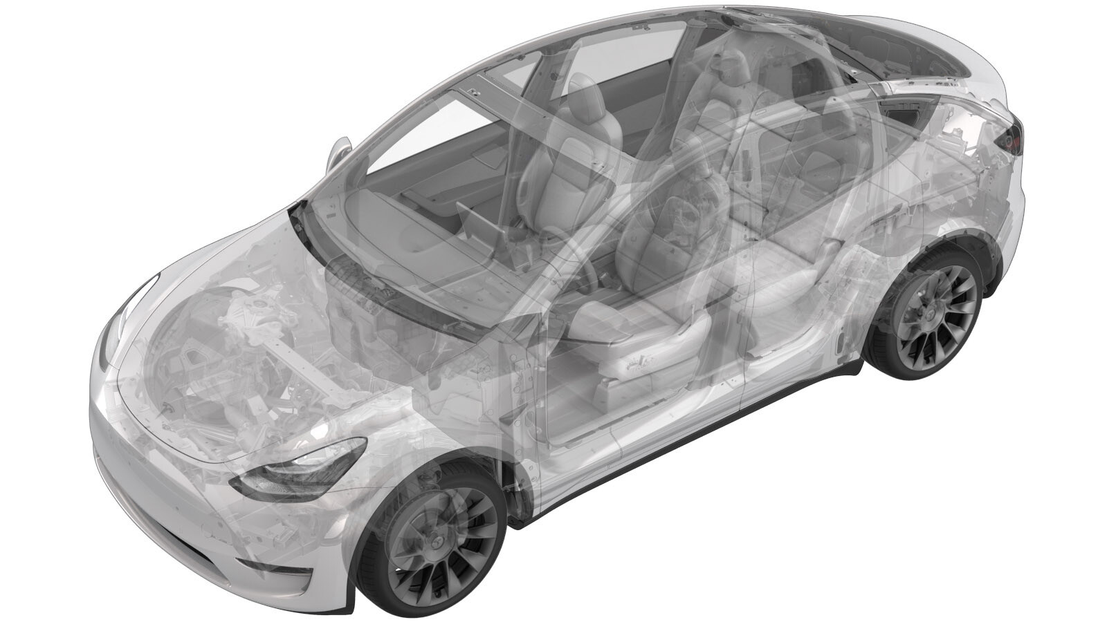
2023-12-18
母排 - 辅助保险丝 - 高压电池(结构化电池组)(拆卸和更换)
 校正代码
16307302 2.40
注意:除非本程序中另有明确规定,否则上述校正代码和 FRT 反映的是执行本程序(包括关联程序)所需的所有工作。除非明确要求,否则请勿堆叠校正代码。
注意:请参阅平均维修工时,深入了解 FRT 及其创建方式。要提供有关 FRT 值的反馈,请发送电子邮件至 ServiceManualFeedback@tesla.com。。
注意:请参阅人员保护,确保在执行以下程序时穿戴适当的个人防护装备 (PPE)。请参阅人体工程学注意事项查看安全健康的作业规程。
警告
本程序为“草案”。虽已通过验证,但可能仍有“警告”和“注意”事项缺失。请遵守安全要求,处理或靠近高压系统和部件时,请谨慎操作。
- Open all the doors and lower all the windows.
-
Place vehicle in service mode with touchscreen
注Hold Tesla T icon at top of center display for four seconds and then type "service" into dialog box
- Remove the ancillary bay cover. See 盖板 - 高压电池仓(结构化电池组)(拆卸和更换).
- 拆下烟火电池隔离开关。请参阅烟火电池断接开关(结构化电池组)(拆卸和安装)。
-
Disconnect HV controller connectors
注7x connectors, Lift hinge upwards to release levered connection
-
Release harness clips from HVC hinge tray and route harness away
注3x clips
-
Remove bolts securing HV controller hinge tray to HV battery
注2x bolts, 8mm, 2 Nm
-
Remove HV controller and tray from ancillary bay
-
Remove 63A fuse cover
注2x securing tabs
-
Disconnect HVIL connector from HV heatpump harness
注1x connector
-
Remove 63A fuse from ancillary bay
注2x nuts, 8mm, 2.5 Nm, Discard after removal
-
Remove inner 63A fuse from ancillary bay
注2x nuts, 8mm, 2.5 Nm, Discard after removal
-
Remove ancillary bay harness from plastic bobbin stud
-
Remove bolts securing PCS to HV battery
注6x bolts, 8mm, 6 Nm, Ensure ONLY the 8mm fasteners are removed, Do not remove the T30 fasteners
-
Remove ancillary bay harness from negative DC link
注1x nut, 8mm, 1.5 Nm, Discard nut after removal
-
Release ancillary bay harness from tray between PCS and bobbin
注1x clip
-
Remove nut securing auxiliary fuse jumper busbar
注1x nut, 8mm, 2.5 Nm, Discard after removal, Slightly shift PCS to gain access to nut, Discard nut after removal
-
Remove auxiliary fuse jumper busbar
-
Install auxiliary fuse jumper busbar
-
Install nut securing auxiliary fuse jumper busbar
注1x nut, 8mm, 2.5 Nm, Install new nut, Shift PCS back into original position
-
Install bolts securing PCS to HV battery
注6x bolts, 8mm, 6 Nm
-
Secure ancillary bay harness onto tray between PCS and bobbin
注1x clip
-
Install ancillary bay harness to negative DC link
注1x nut, 8mm, 1.5 Nm, Install new nut
-
Install ancillary bay harness from plastic bobbin stud
-
Install inner 63A fuse into ancillary bay
注2x nuts, 8mm, 2.5 Nm, Install new nuts
-
Install 63A fuse into ancillary bay
注2x nuts, 8mm, 2.5 Nm, Install new nuts
-
Place holder- Perform Hioki measurement at the joint from 63A fuse to terminal
注1x HV joint, 105µΩ or less, Perform zero adjust to Hioki meter prior to testing
-
Place holder- Perform Hioki measurement at the joint of 63A fuse to auxiliary jumper busbar
注1x HV joint, 105µΩ or less, Perform zero adjust to Hioki meter prior to testing
-
Place holder- Perform Hioki measurement at the joint of inner 63A fuse to flag nut
注1x HV joint, 105µΩ or less, Perform zero adjust to Hioki meter prior to testing
-
Place holder- Perform Hioki measurement at the joint of inner 63A fuse to auxiliary jumper busbar
注1x HV joint, 105µΩ or less, Perform zero adjust to Hioki meter prior to testing
-
Connect HVIL connector onto tray
注1x connector
-
Install 63A fuse cover
注2x securing tabs
-
Position HV controller and tray into ancillary bay
-
Install bolts securing HV controller hinge tray to HV battery
注2x bolts, 8mm, 2 Nm
- 测量烟火电池隔离开关安装点间的电压,然后安装烟火电池隔离开关。请参阅烟火电池断接开关(结构化电池组)(拆卸和安装)。
- Install the ancillary bay cover. See 盖板 - 高压电池仓(结构化电池组)(拆卸和更换).
-
Exit Service Mode through UI
注Controls > Service Mode > Exit Service Mode
- Raise all the windows
-
Close all the doors
注If 12V is powered up, Unlatch rear doors before closing