2024-11-08
泵 - 冷却液 - 电池 - 超级歧管(拆卸和更换)
 校正代码
18401802 0.96
注意:除非本程序中另有明确规定,否则上述校正代码和 FRT 反映的是执行本程序(包括关联程序)所需的所有工作。除非明确要求,否则请勿堆叠校正代码。
注意:请参阅平均维修工时,深入了解 FRT 及其创建方式。要提供有关 FRT 值的反馈,请发送电子邮件至 ServiceManualFeedback@tesla.com。。
注意:请参阅人员保护,确保在执行以下程序时穿戴适当的个人防护装备 (PPE)。
警告
本程序为“草案”。虽已通过验证,但可能仍有“警告”和“注意”事项缺失。请遵守安全要求,处理或靠近高压系统和部件时,请谨慎操作。请将校正内容及反馈发送至ServiceDevelopment@teslamotors.com。
注
If the coolant pump has been replaced twice, escalate a Toolbox
session before proceed.
- Log into Tesla Garage
- Enter vehicle VIN and select "Search"
-
Check Firmware version
注Firmware package installed must be 2021.36 or above for vehicle configuration update and Toolbox routine
- Navigate to "CFG" tab on "Vitals" page
-
Check the coolant pump GTW
configuration, and make sure the configuration is set to
DUAL_MIX.
警告The Coolant Pump Identification will depend on this new configuration.注If the configuration is set to DUAL or DUAL_SAN_P4, change the configuration to DUAL_MIX. If the gateway configuration is already set to DUAL_MIX, no further configuration is required.
- Open LH front door
- Lower LH front window
- Connect to vehicle using Toolbox 3.0
- Select "Dashboards" tab, and select "Infotainment Dashboard"
-
Select "Vehicle Configuration"
注Configuration values should load automatically, if not select "Read Config" and "Run" to load
-
Select "Read Config" and select "Run" to
pull current vehicle configuration, Verify configuration change was performed
注Read config and verify configuration change was successful, Refresh page if required, Select ‘X’ at top right of window to close once complete
- Scroll down to "coolantPumpType" and change to "Two coolant pumps installed, mixed pole pair batches"
-
Select "Apply Changes" and select "Run"
to save updated configuration
注Center display will reboot, Toolbox connection will be lost, Select ‘X’ at top right of window to close once complete
- Select ‘Actions/Autodiag’ and search for ‘Thermal’
-
Select "Start Thermal Fluid Fill/Drain
(Coolant only)", click Run and allow routine to complete
注Select ‘X’ at top right of window to close once complete, Verify vehicle is in Series via Garage > Vitals > Thermal tab > Coolant loops, Thermal Fluid Fill/Drain routine has a 5 hour limit, After 5 hours routine must be performed again
-
Vehicle preparation
注Ensure vehicle is not charging before the repair
- Open hood
-
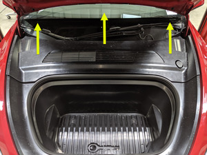
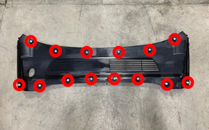
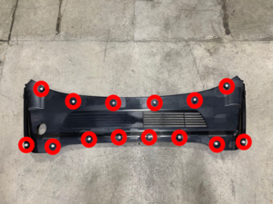
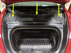
Remove rear apron
注14x clips
-
Power off vehicle from center
display
注Via Controls > Safety & Security > Vehicle Power > Power Off
-
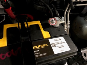
Disconnect 12V negative terminal and
first responders loop
注1x nut, 10mm, 6 Nm, 1x connector, Ensure vehicle is in park, climate control system is off, and vehicle is not charging before disconnecting 12V, Negative terminal should be disconnected before FRL, Allow 2 minutes for all electrical circuits to fully discharge
-
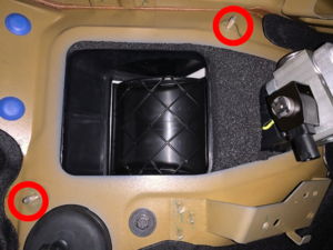
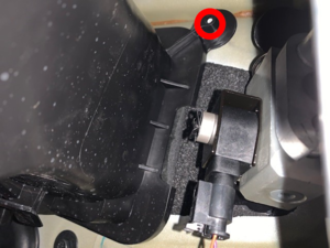
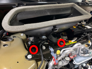
Remove fresh air intake duct
注1x bolt, 10mm, 4 Nm, 2x clips, 1x pin, Remove bolt, Gently pry pin out from thermal beam, then remove from bulkhead studs
-
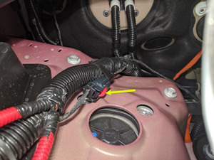
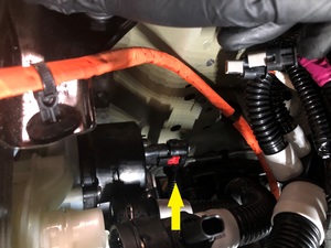
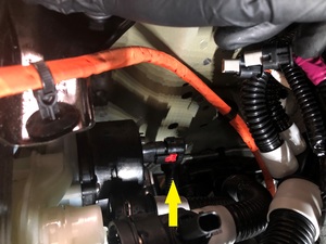
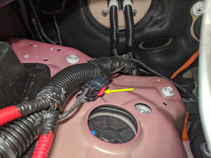
Disconnect powertrain coolant pump
connector
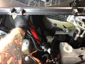
注1x locking electrical connector, Do not push down on Red tab, Pull red tab to disengage lock, Pull again to release connector
-
Disconnect battery coolant pump
connector
注1x locking electrical connector, Do not push down on Red tab, Pull red tab to disengage lock, Pull again to release connector
-
Raise vehicle fully and lower lift onto
locks
注Set vehicle to comfortable working height, Make sure there's an audible click of the locks on both sides before lowering, otherwise vehicle may tilt to the side
-
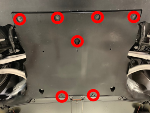
Remove outer fasteners from front aero
shield
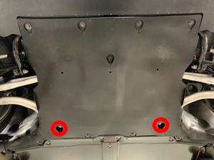
注7x bolts, 10mm, 5 Nm
-
Remove remaining nuts and remove front
aero shield from vehicle
注2x nuts, 15mm, 5 Nm
- Position coolant drain container underneath battery coolant pump
-
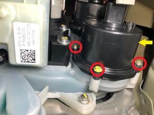
Remove bolts securing battery coolant
pump to Supermanifold
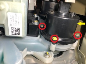
注4x bolts, T20, 1.8 Nm
-
Remove battery coolant pump from
Supermanifold
注Make sure both o-rings (inner purple, and outer black) come off with old pump
-
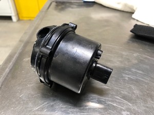
Position battery coolant pump to
Supermanifold and install bolts hand tight
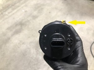
注4x bolts, T20, 1.8 Nm, Lubricate both o-rings with silicone o-ring lubricant, Refer to connector position and install coolant pump with connector tab facing up, Recommend installing upper right bolt with coolant pump for easier installation, Make sure the coolant pump is fully seated
- Remove coolant drain container from underneath vehicle
-
Position the front aero shield to
vehicle and install nuts
注2x nuts, 15mm, 5 Nm
-
Apply Loctite 222 onto front aero shield
bolts and install outer fasteners to front aero shield
注7x bolts, 10mm, 5 Nm
-
Lower vehicle until tires are touching
the ground
注Raise lift off locks, then hold lock release lever to keep locks free while vehicle is lowered
-
Torque bolts securing battery coolant
pump to supermanifold
注4x bolts, T20, 1.8 Nm
-
Connect battery coolant pump
connector
注1x locking electrical connector, Engage locking tab
-
Connect powertrain coolant pump
connector
注1x locking electrical connector, Engage locking tab
- Remove coolant bottle cap
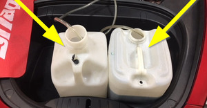
- Place empty coolant container into front storage area
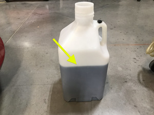
- Fill container with at least 15L of coolant
- Place filled coolant container into front storage area
-
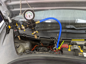
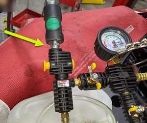
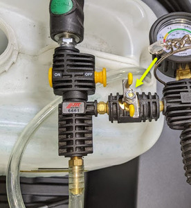
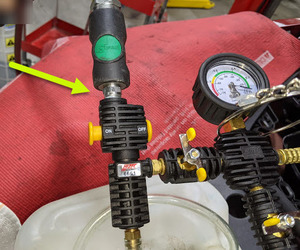
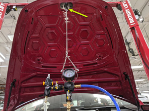
Setup vacuum refill tool
注Verify all valves on refill tool are in the closed position, See image for clarity
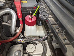
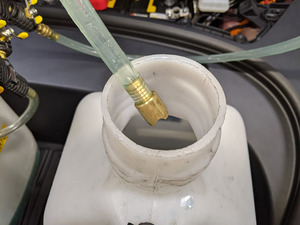
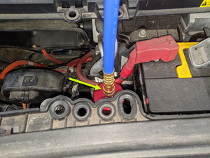
- Install vacuum refill cap onto coolant bottle assembly
-
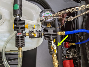
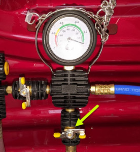
Setup vacuum refill tool
注Verify all valves on refill tool are in the closed position, See image for clarity
-
Install vacuum refill hose into refill
cap on coolant bottle
注Perform push-pull-push test to verify hose is fully installed
- Position overflow hose into empty container
-
Connect shop air supply to coolant
refill tool
注If not already done, Verify refill valve is set to off
-
Open air inlet valve to draw a vacuum,
Once gauge stabilizes, Fully close valve
注Gauge stabilizes roughly (60-70 cmHg), Vacuum should not drop after the valves are closed
-
Slowly open the refill valve to allow
coolant to be drawn into the system
注Make sure hose end of refill hose is fully submerged during entire process
- Once the gauge reads zero, close the refill valve
- Once the gauge reads zero, close the refill valve
- Once the gauge reads zero, close the refill valve
- Once the gauge reads zero, close the refill valve
- Disconnect shop air supply from coolant refill tool
- Remove coolant refill hose from coolant container
- Remove coolant overflow hose from coolant container
- Remove vacuum refill hose from refill cap on coolant bottle
- Remove coolant refill tool from vehicle
- Remove both coolant containers from inside underhood area
-
Connect first responder loop and 12V
negative terminal
注1x nut, 10mm, 6 Nm, 1x connector, Engage locking tab, Connect FRL first before connecting 12V to avoid damage to car computer
-
通过“维护模式”或 Toolbox 执行以下例行程序(请参阅0005 - 维护模式):
PROC_VCFRONT_X_STOP-THERMAL-FILL-DRAINvia Toolbox: (link)via Service Mode:
- Thermal ➜ Actions ➜ Stop Thermal Fill/Drain
- Thermal ➜ Coolant System ➜ Stop Coolant Fill/Drain
- Thermal ➜ Refrigerant System ➜ Stop Refrigerant Fill/Drain
- Drive Inverter ➜ Front Drive Inverter Replacement ➜ Stop Fluid Fill/Drain
- Drive Inverter ➜ Rear Drive Inverter Replacement ➜ Stop Fluid Fill/Drain
- Drive Inverter ➜ Rear Left Drive Inverter Replacement ➜ Stop Fluid Fill/Drain
- Drive Inverter ➜ Rear Right Drive Inverter Replacement ➜ Stop Fluid Fill/Drain
- Drive Unit ➜ Front Drive Unit Replacement ➜ Stop Coolant Fill/Drain
- Drive Unit ➜ Rear Drive Unit Replacement ➜ Stop Coolant Fill/Drain
注Select ‘X’ at top right of window to close once complete -
通过“维护模式”或 Toolbox 执行以下例行程序(请参阅0005 - 维护模式):
TEST_VCFRONT_X_THERMAL-COOLANT-AIR-PURGEvia Toolbox: (link)via Service Mode:
- Thermal ➜ Actions ➜ Coolant Purge Stop or Coolant Purge Start
- Thermal ➜ Coolant System ➜ Coolant Purge Start
- Drive Inverter ➜ Front Drive Inverter Replacement ➜ Coolant Air Purge
- Drive Inverter ➜ Rear Drive Inverter Replacement ➜ Coolant Air Purge
- Drive Inverter ➜ Rear Left Drive Inverter Replacement ➜ Coolant Air Purge
- Drive Inverter ➜ Rear Right Drive Inverter Replacement ➜ Coolant Air Purge
- Drive Unit ➜ Front Drive Unit Replacement ➜ Coolant Air Purge
- Drive Unit ➜ Rear Drive Unit Replacement ➜ Coolant Air Purge
注Make sure vehicle is not in drive state, Plan is still running despite the stop message, Coolant pumps will be audible, Test lasts approximately 10 mins, Speeds can be monitored in garage under PT Thermal tab, Idle speed = ~1500 RPM, Test will vary speeds from 3500-6500 RPM and actuate valve between SERIES and PARALLEL, Putting vehicle into drive state will stop this routine, If speeds hover at 7000 RPM, that means the pumps are air locked, perform vacuum fill again, Continue to add coolant and purge until the coolant level reaches between the NOM and MAX Lines on the bottle, Select ‘X’ at top right of window to close once complete -
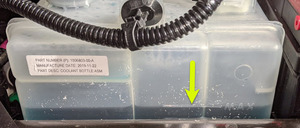
Inspect coolant level and top off as
necessary
注Ensure that the fluid level is at the Max line
- Install coolant bottle cap
-
通过“维护模式”或 Toolbox 执行以下例行程序(请参阅0005 - 维护模式):
TEST-SELF_VCFRONT_X_COOLANT-PUMPS-IDENTIFICATIONvia Toolbox: (link)via Service Mode:
- Thermal ➜ Actions ➜ Run Coolant Pumps Identification
- Thermal ➜ Coolant System ➜ Pump Identification
注Select ‘X’ at top right of window to close once complete, Ensure VCFRONT_a490_coolantPumpsNotIdentified has cleared -
通过“维护模式”或 Toolbox 执行以下例行程序(请参阅0005 - 维护模式):
TEST-SELF_VCFRONT_X_THERMAL-PERFORMANCEvia Toolbox: (link)via Service Mode: Thermal ➜ Actions ➜ Test Thermal Performancevia Service Mode Plus:
- Drive Inverter ➜ Front Drive Inverter Replacement ➜ Thermal System Test
- Drive Inverter ➜ Rear Drive Inverter Replacement ➜ Thermal System Test
- Drive Inverter ➜ Rear Left Drive Inverter Replacement ➜ Thermal System Test
- Drive Inverter ➜ Rear Right Drive Inverter Replacement ➜ Thermal System Test
- Drive Unit ➜ Front Drive Unit Replacement ➜ Thermal System Test
- Drive Unit ➜ Rear Drive Unit Replacement ➜ Thermal System Test
注Select ‘X’ at top right of window to close once complete. -
Install fresh air intake duct
注1x bolt, 10mm bolt, 4 Nm, 2x clips, 1x pin, Set clips on bulkhead studs, Secure to thermal bar
-
Install rear apron
注14x clips, Hold rear wall of frunk to keep from flexing while engaging front clips
- Close hood
-
Remove vehicle from lift
注Lower rack arms fully and remove from under vehicle if necessary, Remove air suspension from "Jack Mode" if equipped
