2026-08-09
铰链托盘 - 控制器 - 高压(拆卸和更换)
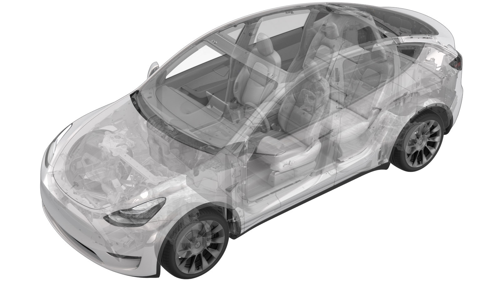 校正代码
16301622 1.32
注意:除非本程序中另有明确规定,否则上文所列校正代码及相关 FRT 反映的是执行本程序(包括关联程序)所需的所有工作。除非明确要求,否则请勿堆叠校正代码。
注意:请参阅平均维修工时,深入了解 FRT 及其创建方式。
注意:请参阅人员保护,确保在执行以下程序时穿戴适当的个人防护装备 (PPE)。注意:请参阅人体工程学注意事项查看安全健康的作业规程。
校正代码
16301622 1.32
注意:除非本程序中另有明确规定,否则上文所列校正代码及相关 FRT 反映的是执行本程序(包括关联程序)所需的所有工作。除非明确要求,否则请勿堆叠校正代码。
注意:请参阅平均维修工时,深入了解 FRT 及其创建方式。
注意:请参阅人员保护,确保在执行以下程序时穿戴适当的个人防护装备 (PPE)。注意:请参阅人体工程学注意事项查看安全健康的作业规程。
警告
本程序为“草案”。虽已通过验证,但可能仍有“警告”和“注意”事项缺失。请遵守安全要求,处理或靠近高压系统和部件时,请谨慎操作。
- Open all four doors
- Lower LH front window
- Move LH front seat forward
- Move RH front seat forward
-
Remove 2nd row seat cushion
注1x connector, Lift front edge of seat cushion upward to release foam from frame
-
Partially remove LH rear door seal
-
Remove LH rear sill trim
注5x clips, Rear edge is mated with groove in trunk side trim, Release clips at the front of LH rear sill trim working your way back towards rear of sill trim
-
Partially remove RH rear door seal
注Pillar and sill trim have tabs seated underneath seal
-
Remove RH rear sill trim
注5x clips, Rear edge is mated with groove in trunk side trim, Release clips at the front of RH rear sill trim working your way back towards rear of sill trim
-
Remove clips securing rear main cabin carpet to vehicle
注3x push clips
-
Remove fasteners securing 40 seat frame to body
注4x bolts, 11mm, 37 Nm, Bottom seat bolts located behind main carpet
-
Fold the 40 seat in down position
注Protect the seat cushion, Do not put weight on seat in folded position without cushion present due to risk of bending the locator tab on the frame
-
Disconnect 40 frame connector
注1x connector
-
Remove 2R 40 seat assembly from vehicle
注Recommend assistance
-
Remove fasteners securing 60 seat frame to body
注5x bolts, 11mm, 37 Nm, Bottom seat bolts located behind main carpet
-
Fold the 60 seat in down position
注Protect the seat back upholstery if necessary, Do not put weight on seat in folded position without cushion present due to risk of bending the locator tab on the frame
-
Disconnect logic connector at LH seat frame
注1x connector
-
Remove 2nd row 60 seat assembly from vehicle
注Recommend assistance
- Open hood
-
Remove rear apron
注14x clips
-
Power off vehicle from center display
注Via Controls > Safety & Security > Vehicle Power > Power Off
-
Disconnect 12V negative terminal and first responders loop
注1x nut, 10mm, 6 Nm, 1x connector, Ensure vehicle is in park, climate control system is off, and vehicle is not charging before disconnecting 12V, Negative terminal should be disconnected before FRL, Allow 2 minutes for all electrical circuits to fully discharge
-
Remove all items from pockets and ensure not wearing metal items
-
Inspect HV insulating gloves
注Check gloves for damage prior to use, Refer to service document TN-15-92-003 R1, for information on inspecting HV gloves. https://service.teslamotors.com/protected-doc/ServiceBulletins/External/TN/TN-15-92-003_High_Voltage_Awareness_Care_Points_R4.pdf
-
Put on HV insulating gloves and leather over gloves
注Make sure to wear Electrical Protective Gloves any time Hioki tester is used
-
Remove the bolts securing ancillary bay probe lid cover to ancillary bay cover
注2x bolts, EP10 5-Lobe, 6 Nm, Discard after removal
-
Remove the ancillary bay probe lid cover from the ancillary bay cover
-
Verify no high voltage
注Make sure to wear PPE (HV gloves, safety glasses) when working on high voltage component, Measure B+ to Ground, B- to Ground, B+ to B-, If voltage is greater than 10V, Pack contactors are not open or welded, Stop work and reach out to Service Engineering
-
Inspect ancillary bay probe lid cover gasket then position onto the ancillary bay cover
注Confirm no visual damage present, Replace gasket if damage is found
-
Install the bolts securing ancillary bay probe lid cover to ancillary bay cover
注2x bolts, EP10 5-Lobe, 6 Nm, Install new rubber washer bolts
- Remove HV insulating gloves
-
Disconnect the HVC logic connector and install logic cap
注1x connector, 1x cap, Release locking tab then push the handle downward to release connector
-
Remove fasteners securing ancillary bay cover to high voltage controller (HVC)
注4x bolts, E10, 5 Nm + 30 degrees, Newer vehicles may be equipped with 3x bolts
-
Remove HVC logic cap
注1x cap
-
Remove bolts securing ancillary bay cover to HV battery
注18x bolts, E10 5-Lobe, 8 Nm, Use E10 5-Lobe socket without magnet, The fasteners are captive and will stay attached to the ancillary bay cover
-
Inspect HV insulating gloves
注Check gloves for damage prior to use, Refer to service document TN-15-92-003 R1, for information on inspecting HV gloves. https://service.teslamotors.com/protected-doc/ServiceBulletins/External/TN/TN-15-92-003_High_Voltage_Awareness_Care_Points_R4.pdf
-
Put on HV insulating gloves and leather over gloves
注Make sure to wear Electrical Protective Gloves any time Hioki tester is used
-
Remove ancillary bay cover from HV battery
注Inspect the ancillary bay for any missing insulators, Install any missing insulators that are accessible before continuing to next step
-
Install the battery pyro and shunt insulators
注2x insulators
-
Install the HV joint insulator onto positive pack contactor
注1x insulator
-
Install the HV joint insulator to negative pack contactor
注1x insulator
-
Install the insulator for DC input assembly to both fastcharge busbars inlet side
注2x insulators
-
Install the negative AC inlet terminal cover
注1x cover, 3x clips, Use caution as the clips are very easy to damage
-
Install the positive AC inlet terminal cover
注1x cover, 3x clips, Use caution as the clips are very easy to damage
-
Install fuses access insulator
注3x clips
-
Install HVC logic cap
注1x cap
- 拆下烟火电池隔离开关。请参阅烟火电池断接开关(拆卸和更换)。
-
Disconnect HV controller connectors
注7x connectors
-
Remove the megaharness clips from HV controller hinge tray
注5x harness clips
-
Remove bolts securing hinge tray onto HV controller
注2x bolts, E6, 2 Nm
-
Remove the HV hinge tray from ancillary bay assembly
注2x pivot clips, Pull upward and release from pivot clips
-
Install the HV hinge tray to ancillary bay assembly
注2x pivot clips, Position hinge tray onto pivot clips and push down to secure into clips
-
Install bolts securing hinge tray onto HV controller
注2x bolts, E6, 2 Nm
-
Connect HV controller connectors
注7x connectors
-
Install the megharness clips to HV controller hinge tray
注5x clips
-
Remove fuse access insulator
注3x clips, Lift straight up off of the fuses
- 测量烟火电池隔离开关安装点间的电压,然后安装烟火电池隔离开关。请参阅烟火电池断接开关(拆卸和更换)。
-
Remove the insulator for DC input assembly to both fastcharge busbar inlet side
注2x insulators
-
Remove the HV joint insulator from positive pack contactor
注1x insulator
-
Remove the HV joint insulator from negative pack contactor
注1x insulator
-
Clean HVC studs and ancillary bay cover underside with isopropyl alcohol
注4x studs
-
Inspect ancillary bay walls for damage
注Any dent or depression in the seal that causes it to not be flat will result in a leak, and cannot be reused, Any paint that comes off the ancillary bay wall, whether or not it sticks to the seal, will require enclosure leak test when reassembled, It can still be reused
-
Inspect ancillary bay cover seal to confirm it has no visual damage
注Image up close for clarity, Delaminated and torn seals cannot be reused
-
Remove HVC logic cap
注1x cap
-
Position the ancillary bay cover to HV battery for installation
注Ensure all accessible insulators are present, wearing Electrical Protective Gloves is not necessary once all HV components are covered.
-
Install HVC logic cap
注1x cap
-
Install bolts securing ancillary bay cover to HV battery
注18x bolts, E10 5-Lobe, 8 Nm, Use E10 5-Lobe socket without magnet, Fasteners are captive, Follow torque sequence per image
-
Install fasteners securing ancillary bay cover to high voltage controller (HVC)
注4x bolts, E10, 5 Nm + 30 degrees, Newer vehicles may be equipped with 3x bolts
- Remove HV insulating gloves
-
Remove logic cap and connect the HVC logic connector
注1x connector, 1x cap, Align connector then pull the handle to locking position get connector fully seated
-
Install 2R 40 seat assembly into vehicle
注Recommend assistance
-
Connect 40 seat frame connector to body harness
注1x connector
-
Fold the 40 seat into vertical position
注Remove seat cushion protection
-
Secure 40 seat frame to vehicle
注4x bolts, 11mm, 37 Nm, Bottom seat bolts located behind main carpet, Torque in sequence; Outboard front -> Inboard rear -> Outboard rear -> Inboard front
-
Install RH rear sill trim
注5x clips, Rear edge is mated with groove in trunk side trim, Install rear edge of RH rear sill trim into trunk side trim and work your way forward securing clips
-
Reseat RH rear door seal
注Seat pillar and sill trim tabs underneath seal
-
Install 2nd row 60 seat assembly
注Recommend assistance
-
Connect logic connector at LH seat frame
注1x connector
-
Fold the 60 seat into vertical position
注Remove seat back protection if necessary
-
Install fasteners securing 60 seat frame to body
注5x bolts, 11mm, 37 Nm, Bottom seat bolts located behind main carpet, Torque in sequence; Outboard front -> Both inboard rear -> Outboard rear -> Inboard front
-
Install LH rear sill trim
注5x clips, Rear edge is mated with groove in trunk side trim, Install rear edge of LH rear sill trim into trunk side trim and work your way forward securing clips
-
Reseat LH rear door seal
注Seat pillar and sill trim tabs underneath seal
-
Install clips securing rear main cabin carpet to vehicle
注3x push clips
-
Install 2nd row seat cushion
注1x connector, Slide rear cushion rearward then align foam with seat rail, Make sure cushion is fully seated with push & pull test
-
Connect first responder loop and 12V negative terminal
注1x nut, 10mm, 6 Nm, 1x connector, Engage locking tab, Connect FRL first before connecting 12V to avoid damage to car computer
-
Install rear apron
注14x clips, Hold rear wall of frunk to keep from flexing while engaging front clips
- Close hood
- Move LH front seat to original position
- Move RH front seat to original position
- Raise all four windows
-
Close all four doors
注If 12V is powered up, Unlatch rear doors before closing