Assembly - Tail Lamp - Liftgate (Model Y L) (Remove and Install)
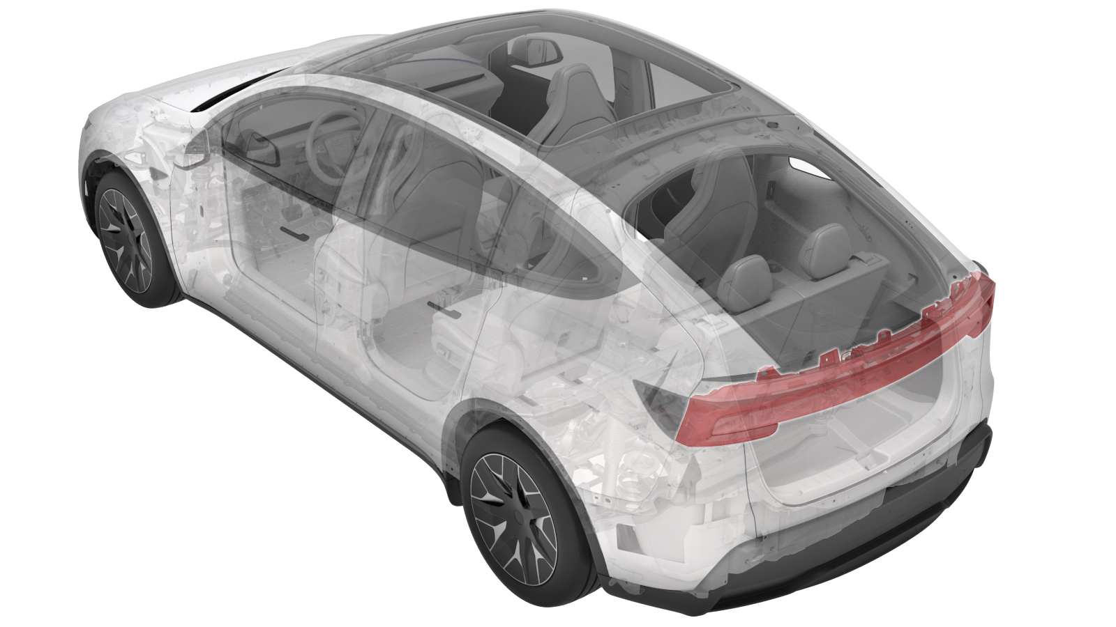 Correction code
17401800001
FRT
0.42
NOTE: Unless
otherwise explicitly stated in the procedure, the correction code and its
associated FRT reflect all of the work required to perform this procedure,
including the linked procedures. Do not stack correction
codes unless explicitly told to do so.
NOTE: See Flat Rate Times to
learn more about FRTs and how they are created.
NOTE: See Personal Protection to make
sure you are wearing proper PPE when performing the procedure below.
NOTE: See Ergonomic Precautions for safe and healthy
working practices.
Correction code
17401800001
FRT
0.42
NOTE: Unless
otherwise explicitly stated in the procedure, the correction code and its
associated FRT reflect all of the work required to perform this procedure,
including the linked procedures. Do not stack correction
codes unless explicitly told to do so.
NOTE: See Flat Rate Times to
learn more about FRTs and how they are created.
NOTE: See Personal Protection to make
sure you are wearing proper PPE when performing the procedure below.
NOTE: See Ergonomic Precautions for safe and healthy
working practices.
- 2026-08-14: Due to part changes, removed the liftgate camera and handle steps and added liftgate extension harness steps.
Torque Specifications
| Description | Torque Value | Recommended Tools | Reuse/Replace | Notes |
|---|---|---|---|---|
| Bolts (x4) that attach the lamp to the liftgate |
 4 Nm (2.9 lbs-ft) |
|
Reuse | |
| Nuts (x2) that attach the lamp to the liftgate |
5 Nm (3.7 lbs-ft) |
|
Reuse | |
| Bolts (x3) that attach the lamp to the liftgate |
3.5 Nm (2.6 lbs-ft) |
|
Reuse |
Remove
- Remove the spoiler assembly. See Spoiler Assembly (Model YL) (Remove and Install).
-
Disconnect the liftgate extend harness
connectors (x2).
-
Remove the liftgate extend harness
from the liftgate assembly.
NotePay attention to the grommet installed orientation and the harness route path on both sides of the liftgate, so that the harness can be installed to its original position during installation.
-
Remove the bolts (x4) that attach the
lamp to the liftgate.
TipUse of the following tool(s) is recommended:
- Torx T30 socket
-
Remove the nuts (x2) that attach the
lamp to the liftgate.
TipUse of the following tool(s) is recommended:
- 10 mm deep socket
-
Remove the bolts (x3) that attach the
lamp to the liftgate.
TipUse of the following tool(s) is recommended:
- 10 mm deep socket
-
Release the clips (x4) to remove the
tail lamp assembly from the liftgate.
Install
-
Align the location pins (x3) to the
holes on the body, and then secure the clips (x4) to install the tail lamp assembly to
the liftgate.
-
Install the exterior bolts (x3) that
attach the lamp to the liftgate.3.5 Nm (2.6 lbs-ft)TipUse of the following tool(s) is recommended:
- 10 mm deep socket
-
Install the bolts (x4) that attach the
lamp to thee liftgate.4 Nm (2.9 lbs-ft)TipUse of the following tool(s) is recommended:
- Torx T30 socket
-
Install the nuts (x2) that attach the
lamp to the liftgate.5 Nm (3.7 lbs-ft)TipUse of the following tool(s) is recommended:
- 10 mm deep socket
-
Install the liftgate extend harness to
the liftgate assembly and install the grommet.
NoteInstall the grommet in the same orientation as removed and make sure that the harness is routed correctly.
-
Connect the liftgate extend harness
connectors (x2).
- Install the spoiler assembly. See Spoiler Assembly (Model YL) (Remove and Install).
- Place the vehicle in Service Mode by using the touchscreen. See Service Mode.
- Unlock the vehicle gateway. See Gateway (Unlock).
-
On the touchscreen, tap the Service
Mode "wrench" (at the bottom of the touchscreen UI), and then tap , select
RearView
in theCamera Selection
drop list, click Run, and allow the routine to complete. - Exit Service Mode. See Service Mode.
- Raise the LH front window and close the LH front door.
- Inform the customer that the vehicle needs to be driven by the customer to complete the calibration procedure.