PT Sensor - High Pressure (Remove and Replace)
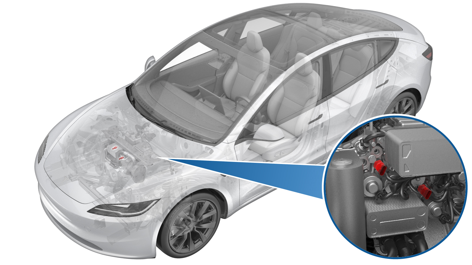 Correction code
1840010132
FRT
0.30
NOTE: Unless
otherwise explicitly stated in the procedure, the correction code and its
associated FRT reflect all of the work required to perform this procedure,
including the linked procedures. Do not stack correction
codes unless explicitly told to do so.
NOTE: See Flat Rate Times to
learn more about FRTs and how they are created.
NOTE: See Personal Protection to make
sure you are wearing proper PPE when performing the procedure below.
NOTE: See Ergonomic Precautions for safe and healthy
working practices.
- 2026-11-12: Added steps to completely remove the A/C lines to avoid excessive bending.
- 2024-01-29: Updated steps to ensure consistency of thermal system related procedures.
Equipment:
- 1711245-00-A Snap On Ecotechnics Dual GAS AC Machine
- 1600833-00-A GEN 2 P/T SENSOR SOCKET, 24 MM
Torque Specifications
| Description | Torque Value | Recommended Tools | Reuse/Replace | Notes |
|---|---|---|---|---|
| Bolt that attaches the supermanifold-to-compressor A/C line to the supermanifold |
 22 Nm (16.2 lbs-ft) |
|
Reuse | |
| High Pressure Pressure and Temperature Sensor |
9 Nm (6.6 lbs-ft) |
|
N/A |
|
Remove
- Remove the underhood storage unit. See Underhood Storage Unit (Remove and Replace).
- Unlock the vehicle gateway. See Gateway Unlock.
- On the touchscreen, touch and select Run to start the "Start Thermal Fill Drain (Refrigerant Only)" routine.
- Recover the A/C refrigerant (refrigerant only). See A/C Refrigerant (Recovery and Recharge) (Restore).
- On the vehicle touchscreen, tap and make sure that the refrigerant system pressure is at atmospheric level (approx. 1 bar).
-
Power off the vehicle from the center
display.
NoteOn the touchscreen, touch .
- Remove the AC hoses from the vehicle.
-
Carefully depress the Schrader valves (x2) to level out any pressure difference between the A/C system pressure and the actual ambient atmospheric pressure.
CAUTIONMake sure to depress both Schrader valves. Failure to do so may result in injury.
-
Remove the nut that attaches the low pressure fitting to the compressor, then move
the line aside for clearance.
NoteUse of the following tool(s) is recommended:
- 13 mm deep socket
-
Remove the nut that attaches the high pressure fitting to the compressor, then move
the line aside for clearance.
NoteUse of the following tool(s) is recommended:
- 13 mm deep socket
-
Remove the bolt that attaches the
supermanifold-to-compressor A/C line to the supermanifold.
TipUse of the following tool(s) is recommended:
- 13 mm socket
-
Remove the supermanifold-to-compressor
A/C line from the supermanifold, and move it aside.
NoteCarefully position the line so that oil does not drip out.
-
Release the locking tab, and then
disconnect the electrical connector from the high pressure and temperature sensor.
CAUTIONDO NOT push down on the red locking tab. Pull the tab away from the connector until the connector is unlocked, and then continue pulling the main body of the connector to fully disconnect it.WarningThe video(s) included in this procedure are meant as an overview for supplemental purposes only. Follow all of the steps listed in the procedure to avoid damage to components and/or personal injury.
-
Use the P/T sensor socket to remove
the high pressure temperature sensor from the supermanifold.
CAUTIONUse only hand tools to remove the PT sensor. Impact or power tools will break the threads.CAUTIONUse only the P/T sensor socket to remove the sensor. Using other tools can damage the connector housing.TipUse of the following tool(s) is recommended:
- GEN 2 P/T SENSOR SOCKET, 24 MM
- Record the part numbers and serial numbers of the old and new sensors in the repair order.
Install
- Lubricate the new high pressure temperature sensor threads and O-ring with the appropriate A/C oil. See Fluids and Capacities for A/C oil specifications.
-
Install and hand-tighten the high
pressure temperature sensor until the sensor O-ring just makes contact with the
Supermanifold.
NoteUse an inspection mirror to visualize this and subsequent steps.WarningThe video(s) included in this procedure are meant as an overview for supplemental purposes only. Follow all of the steps listed in the procedure to avoid damage to components and/or personal injury.
- Manually back off and tighten the high pressure temperature sensor in an incremental manner so that the sensor O-ring properly slides into the chamfer in the Supermanifold.
- If the high pressure temperature sensor O-ring appears to pinch, or no longer slides into the chamfer, stop and reverse thread the sensor until the O-ring no longer appears to be pinched.
-
Continue to back off and tighten the
high pressure temperature sensor until the O-ring slides completely into the chamfer and
is no longer visible.
NoteThere should be no gap, and the sensor body should be bottomed out against the Supermanifold.
-
Use the P/T sensor socket to tighten
the high pressure temperature sensor to the specified torque value.9 Nm (6.6 lbs-ft)CAUTIONUse only hand tools to install the PT sensor. Impact or power tools will break the threads.CAUTIONUse only the P/T sensor socket to install the sensor. Using other tools can damage the sensor.TipUse of the following tool(s) is recommended:
- GEN 2 P/T SENSOR SOCKET, 24 MM
-
Connect the electrical connector on
the high pressure and temperature sensor.
CAUTIONPush the red locking tab towards the connector to engage the locking mechanism. DO NOT push down or pull up on the red locking tab.
-
Install new seal washers on the
supermanifold side of the supermanifold-to-compressor A/C line, and then lubricate the
washers with a small amount of the appropriate A/C oil. See Fluids and Capacities for A/C oil specifications.
-
Replace the seal washer on the high side pipe, lubricating the new seal washer with
ND-11 oil prior to installation.
-
Replace the seal washer on the low side pipe, lubricating the new seal washer with
ND-11 oil prior to installation.
-
Install the nut that attaches the high pressure fitting to the compressor.22 Nm (16.2 lbs-ft)NoteUse of the following tool(s) is recommended:
- 13 mm socket
-
Install the nut that attaches the low pressure fitting to the compressor.22 Nm (16.2 lbs-ft)NoteUse of the following tool(s) is recommended:
- 13 mm socket
-
Position the
supermanifold-to-compressor A/C line on the supermanifold, and then hand tighten the
bolt that attaches the A/C line to the supermanifold.
-
Tighten the bolt that attaches the A/C
line to the supermanifold.22 Nm (16.2 lbs-ft)TipUse of the following tool(s) is recommended:
- 13 mm socket
- Install the AC hoses to the vehicle.
- Perform the vacuum leak test and oil injection. See Vacuum Leak Test and Oil Injection.
-
Recharge the A/C refrigerant. See
A/C Refrigerant (Recovery and Recharge) (Restore).
NoteDo not disconnect the laptop from the vehicle yet.
- Remove the AC hoses from the vehicle.
- Install caps onto the AC ports.
- If a refrigerant leak detector is available, make sure that there is no leak at the high pressure temperature sensor.
- On the touchscreen, tap the Service Mode "wrench" (at the bottom of the touchscreen UI), and then tap , click Run, and allow the routine to complete.
- Select , select the START next to Test Thermal Performance, click Run, and allow the routine to complete.
- Select , select the START next to Test HVAC Performance, click Run, and allow the routine to complete.
- Exit Service Mode through UI. See Service Mode.
- Install the underhood storage unit. See Underhood Storage Unit (Remove and Replace).