2026-03-16
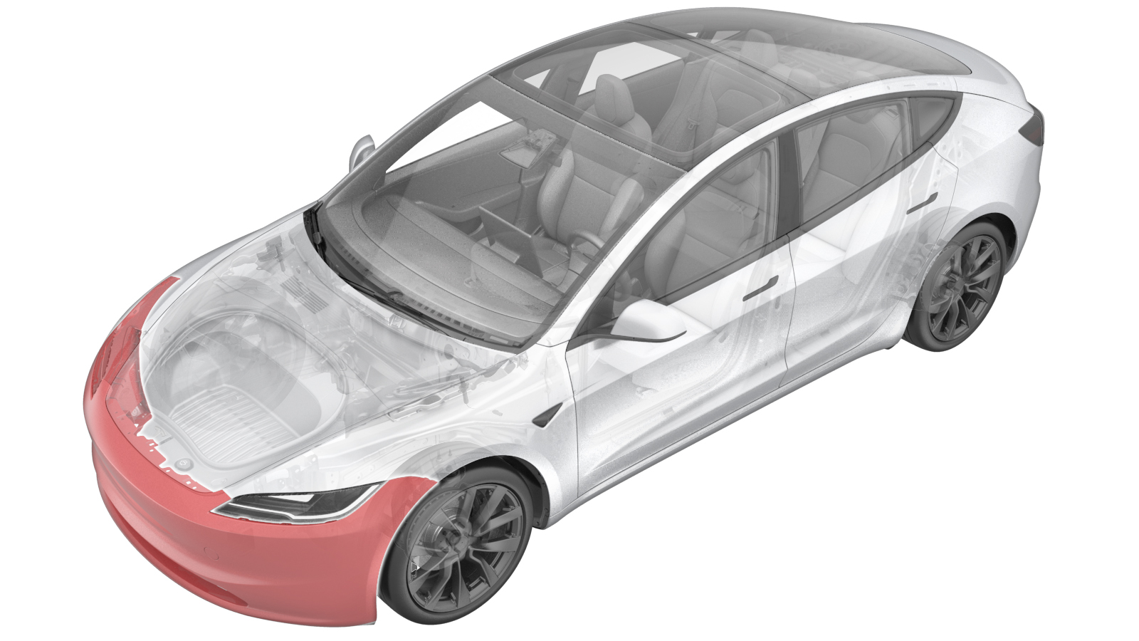
Fascia - Front (Remove and Replace)
 Correction code
1001020042
FRT
0.90
NOTE: Unless otherwise explicitly stated in the procedure, the correction code and FRT listed above reflect all of the work required to perform this procedure, including the linked procedures. Do not stack correction codes unless explicitly told to do so.
NOTE: See Flat Rate Times to learn more about FRTs and how they are created.
NOTE: See Personal Protection to make sure you
are wearing proper PPE when performing the procedure below.
NOTE: See Ergonomic Precautions for safe and healthy working practices.
Correction code
1001020042
FRT
0.90
NOTE: Unless otherwise explicitly stated in the procedure, the correction code and FRT listed above reflect all of the work required to perform this procedure, including the linked procedures. Do not stack correction codes unless explicitly told to do so.
NOTE: See Flat Rate Times to learn more about FRTs and how they are created.
NOTE: See Personal Protection to make sure you
are wearing proper PPE when performing the procedure below.
NOTE: See Ergonomic Precautions for safe and healthy working practices.
- 2025-12-18: Added steps to install the fender brackets onto the front fascia.
- 2025-10-22: Added steps relate to the front fascia camera.
Remove
- Remove the front fascia assembly. See Fascia - Front (Remove and Install).
-
Release the clip that attaches the
front fascia harness to the tow hook cover.
-
Disconnect the electrical connector
from the front fascia camera.
NoteThis connector may not be present on early production vehicles. If not, skip this step.
-
Disconnect the electrical connector
from the pedestrian warning speaker.
-
Use a clip prytool to release the
clips (x9) that attach the front fascia harness to the front fascia, then remove the
front fascia harness.
-
Remove the front valance. See Valance - Front Fascia (Remove and Replace).
NoteNo need to remove the pedestrian warning speaker from the valance.
- Remove the fascia grille. See Grille - Fascia - Front (Remove and Replace).
-
Remove the B-nuts (x8) from the front
fascia.
NotePush both side lock pieces to release the nuts.
Install
-
Install the B-nuts (x8) to the front
fascia.
NoteReplace any nuts if damaged.NoteMake sure that the nuts are fully in place.
- Install the fascia grille. See Grille - Fascia - Front (Remove and Replace).
- Install the front valance. See Valance - Front Fascia (Remove and Replace).
-
Install the clips (x9) that attach the
front fascia harness to the front fascia.
-
Connect the electrical connector to
the pedestrian warning speaker.
-
Connect the electrical connector to
the front fascia camera.
NoteThis connector may not be present on early production vehicles. If not, skip this step.
-
Install the clip that attaches the
front fascia harness to the tow hook cover.
-
Place a new LH fender bracket (1734299-00-H) onto the LH fascia, securing it with 2
new rivets (1064496-00-A).
-
Place a new RH fender bracket (1734300-00-H) onto the RH fascia, securing it with 2
new rivets (1064496-00-A).
- Install the front fascia assembly. See Fascia - Front (Remove and Install).
- Connect a laptop with Toolbox to the vehicle. See Toolbox (Connect and Disconnect).
- Perform the following routine using Service Mode or Toolbox (see 0005 - Service Modes): PROC_DAS_X_ENTER-CALIBRATION-MODEvia Toolbox:(link)
- Perform the following routine using Service Mode or Toolbox (see 0005 - Service Modes): PING-HTTP_DAS_X_FASCIA-CAMERA-SCRIPTvia Toolbox:(link)
- Perform the following routine using Service Mode or Toolbox (see 0005 - Service Modes): PROC_DAS_X_EXIT-CALIBRATION-MODEvia Service Mode Plus:Driver Assist ➜ Cameras ➜ Exit Factory Calibration Modevia Toolbox:(link)
- Disconnect the laptop with Toolbox from the vehicle.
- Exit Service Mode. See Service Mode.