Active Grille Shutter (Remove and Replace)
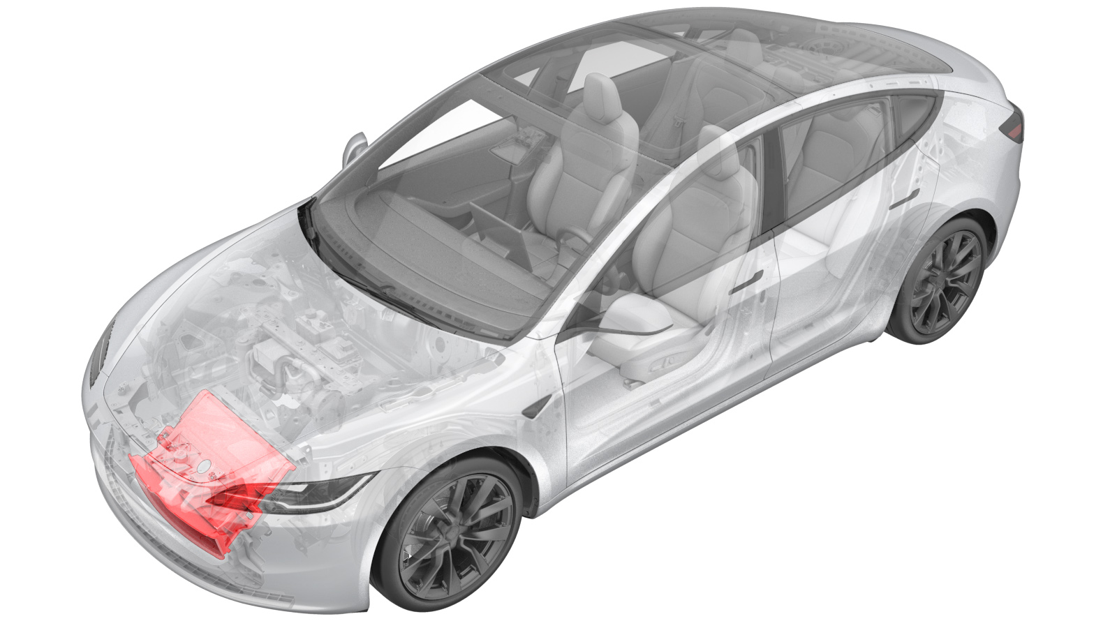 Correction code
1850010012
FRT
0.66
NOTE: Unless
otherwise explicitly stated in the procedure, the correction code and its
associated FRT reflect all of the work required to perform this procedure,
including the linked procedures. Do not stack correction
codes unless explicitly told to do so.
NOTE: See Flat Rate Times to
learn more about FRTs and how they are created.
NOTE: See Personal Protection to make
sure you are wearing proper PPE when performing the procedure below.
NOTE: See Ergonomic Precautions for safe and healthy
working practices.
Correction code
1850010012
FRT
0.66
NOTE: Unless
otherwise explicitly stated in the procedure, the correction code and its
associated FRT reflect all of the work required to perform this procedure,
including the linked procedures. Do not stack correction
codes unless explicitly told to do so.
NOTE: See Flat Rate Times to
learn more about FRTs and how they are created.
NOTE: See Personal Protection to make
sure you are wearing proper PPE when performing the procedure below.
NOTE: See Ergonomic Precautions for safe and healthy
working practices.
- 2026-09-17: Reorganized the procedure as the active grille shutter can be removed without removing the cooling fan module.
- 2026-05-11: Added the PROC_VCFRONT_X_LOUVER-CALIBRATION routine.
Remove
- Raise and support the vehicle. See Raise Vehicle - 2 Post Lift.
- Disconnect the LV power. See LV Power (Disconnect and Connect) (Modify).
- Remove the underhood storage unit. See Underhood Storage Unit (Remove and Replace).
-
Remove the bolts (x3) that secure the washer tank to the front end carrier and move
the washer tank aside.
NoteUse of the following tool(s) is recommended:
- 2 in extension
- 10 mm socket
-
Carefully remove the ambient
temperature sensor cover from the active grille shutter.
-
Disconnect the ambient temperature
sensor electrical connector and remove the sensor from the active grille shutter.
-
Release the connector lock, and then
disconnect the active grille shutter actuator electrical connector.
CAUTIONDo not push down on the red tab. Pull the red tab to release the connector lock.
-
Release the upper and middle locking tabs (x8) that attach the active grille shutter
to the cooling fan module.
- Remove the front aero shield panel. See Panel - Aero Shield - Front (Remove and Replace).
- Remove the front valance. See Valance - Front Fascia (Remove and Replace).
-
Place a towel to the front of the subframe to protect the cooling fan.
-
Remove the LH and RH bolts that attach the bottom of the condenser fan module to the
ankle catcher.
NoteUse of the following tool(s) is recommended:
- 8 mm socket
- Ratchet/torque wrench
NoteHold the condenser fan module to ease the removal of the bolts. -
Release the lower locking tabs (x6) that attach the active grille shutter to the
cooling fan module.
- Lower the vehicle fully.
-
Remove the active grille shutter from the vehicle.
CAUTIONBe careful not to damage the radiator.
Install
-
Install the active grille shutter onto the cooling fan module, then fasten the upper
and middle locking tabs (x8).
- Raise the vehicle fully and lower the lift onto locks.
-
Fasten the lower locking tabs (x6) that attach the active grille shutter to the
cooling fan module.
-
Install and hand-tighten the LH and RH bolts (x2) that attach the bottom of the
condenser fan module to the ankle catcher.
NoteGently lift the condenser fan module to position into place and install the bolts.
-
Torque the bolts that attach the bottom of the condenser fan module to the ankle
catcher.
 10 Nm (7.4 lbs-ft)NoteUse of the following tool(s) is recommended:
- 8 mm socket
- Ratchet/torque wrench
- Remove the towel from the front of the subframe.
- Install the front valance. See Valance - Front Fascia (Remove and Replace).
- Install the front aero shield panel. See Panel - Aero Shield - Front (Remove and Replace).
- Lower the vehicle fully.
-
Install the ambient temperature sensor
into the active grill shutter and connect the electrical connector.
-
Install the ambient temperature sensor
cover to the active grille shutter.
-
Connect the active grille shutter
actuator electrical connector, then engage the connector lock.
-
Connect the LV power. See LV Power (Disconnect and Connect) (Modify).
NoteDo not install the rear underhood apron at this time.
-
Install the bolts (x3) that secure the washer tank to the front end carrier.3 Nm (2.2 lbs-ft)NoteUse of the following tool(s) is recommended:
- 2 in extension
- 10 mm socket
- Install the underhood storage unit. See Underhood Storage Unit (Remove and Replace).
- Perform the following routine using Service Mode or Toolbox (see 0005 - Service Modes): PROC_VCFRONT_X_LOUVER-CALIBRATIONvia Toolbox:(link)
-
Perform the following routine using Service Mode or Toolbox: TEST-SELF_VCFRONT_X_THERMAL-PERFORMANCEvia Service Mode:Thermal ➜
Actions ➜ Test Thermal Performancevia Service Mode Plus:
- Drive Inverter ➜ Front Drive Inverter Replacement ➜ Thermal System Test
- Drive Inverter ➜ Rear Drive Inverter Replacement ➜ Thermal System Test
- Drive Inverter ➜ Rear Left Drive Inverter Replacement ➜ Thermal System Test
- Drive Inverter ➜ Rear Right Drive Inverter Replacement ➜ Thermal System Test
- Drive Unit ➜ Front Drive Unit Replacement ➜ Thermal System Test
- Drive Unit ➜ Rear Drive Unit Replacement ➜ Thermal System Test
- Exit Service Mode or disconnect the laptop if applicable (see 0005 - Service Modes).
- Raise the windows and close the doors.
- Remove the vehicle from the lift.