2026-03-16
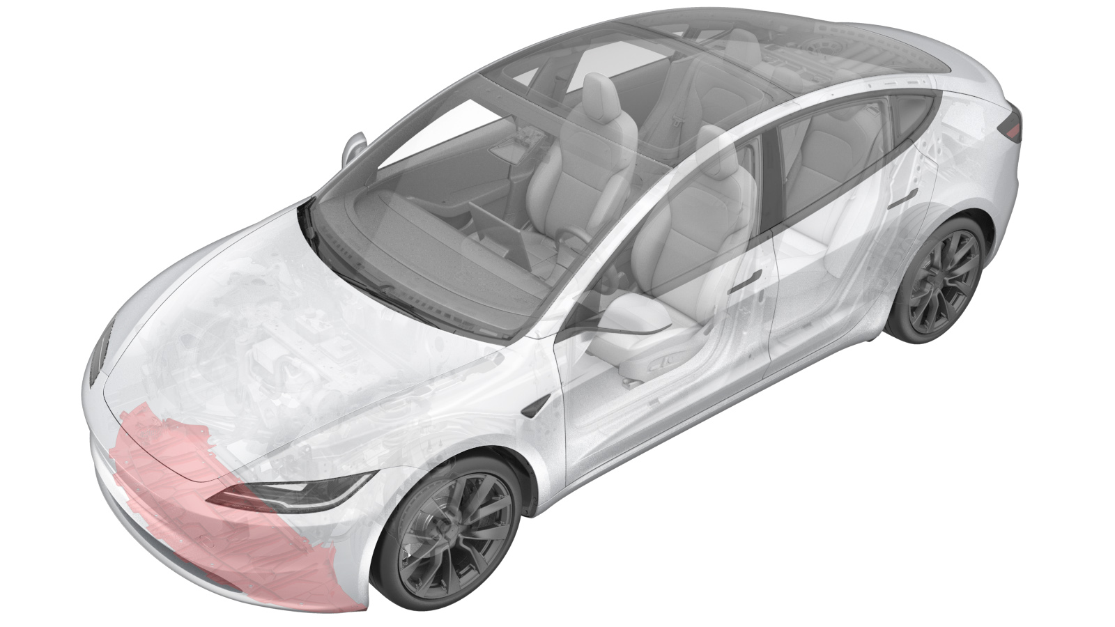
Valance - Front Fascia (Remove and Replace)
 Correction code
1203010052
FRT
0.30
NOTE: Unless otherwise explicitly stated in the procedure, the correction code and FRT listed above reflect all of the work required to perform this procedure, including the linked procedures. Do not stack correction codes unless explicitly told to do so.
NOTE: See Flat Rate Times to learn more about FRTs and how they are created.
NOTE: See Personal Protection to make sure you
are wearing proper PPE when performing the procedure below.
NOTE: See Ergonomic Precautions for safe and healthy working practices.
Correction code
1203010052
FRT
0.30
NOTE: Unless otherwise explicitly stated in the procedure, the correction code and FRT listed above reflect all of the work required to perform this procedure, including the linked procedures. Do not stack correction codes unless explicitly told to do so.
NOTE: See Flat Rate Times to learn more about FRTs and how they are created.
NOTE: See Personal Protection to make sure you
are wearing proper PPE when performing the procedure below.
NOTE: See Ergonomic Precautions for safe and healthy working practices.
- 2026-03-16: Added notes and tools for bolts securing front valance to front fascia on newer vehicles.
Note
The images in this repair procedure show
a Non-Performance vehicle. The instructions apply to both the Non-Performance and the
Performance version.
Torque Specifications
| Description | Torque Value | Recommended Tools | Reuse/Replace | Notes |
|---|---|---|---|---|
| Screws (x3) that attach the pedestrian warning speaker to the valance |
 1.8 Nm (1.3 lbs-ft) |
|
Reuse | |
| Bolts (x8) that attach the valance to the fascia |
3 Nm (2.2 lbs-ft) |
|
Reuse | |
| Nuts (x2) at the LH and RH corners of the valance |
3 Nm (2.2 lbs-ft) |
|
Reuse |
Remove
- Remove the front aero shield panel. See Panel - Aero Shield - Front (Remove and Replace).
-
Remove the push clips (x6)
that attach the LH and RH sides of the valance to the wheel arch
liners.
NoteRemove the outer clips as necessary to allow for easier access to the nuts behind the wheel liner.
-
Remove the nuts (x2) at the
LH and RH corners of the valance.
NoteThe nuts are accessed from behind the front of the wheel arch liners.TIpUse of the following tool(s) is recommended:
- 10 mm socket
-
Release the clip that attaches the pedestrian warning harness to the
speaker, and then disconnect the pedestrian warning connector.
NoteThe connector access may vary depending on the version of the super horn audio speaker installed on the vehicle.
-
Remove the bolts (x8) that
attach the valance to the front fascia, and then remove the valance from the
vehicle.
NoteNewer vehicles are equipped with 6 T40 bolts and 2 10mm bolts.TIpUse of the following tool(s) is recommended:
- Torx T40 socket
- (If equipped) 10 mm socket
-
Remove the screws (x3) that attach the pedestrian warning speaker to the
valance, and then remove the speaker from the valance.
TIpUse of the following tool(s) is recommended:
- Torx T25 socket
Install
-
Install the pedestrian
warning speaker to the valance, and then install the screws (x3) that attach
the pedestrian warning speaker to the valance.1.8 Nm (1.3 lbs-ft)TIpUse of the following tool(s) is recommended:
- Torx T25 socket
-
Install the valance to the
front fascia, and install the bolts (x8) that attach the valance to the
fascia.3 Nm (2.2 lbs-ft)NoteNewer vehicles are equipped with 6 T40 bolts and 2 10mm bolts.TIpUse of the following tool(s) is recommended:
- Torx T40 socket
- (If equipped) 10 mm socket
-
Connect the pedestrian warning connector, and then install the clip that
attaches the pedestrian warning harness to the speaker.
-
Install the nuts (x2) at the
LH and RH corners of the valance.3 Nm (2.2 lbs-ft)NoteThe nuts are accessed from behind the front of the wheel liners.TIpUse of the following tool(s) is recommended:
- 10 mm socket
-
Install the push clips (x6)
that attach the LH and RH sides of the valance to the wheel liners.
- Install the front aero shield panel. See Panel - Aero Shield - Front (Remove and Replace).