DC Harness - Power Conversion System (PCS2 Lite) (Model 3 Standard) (Remove and Replace)
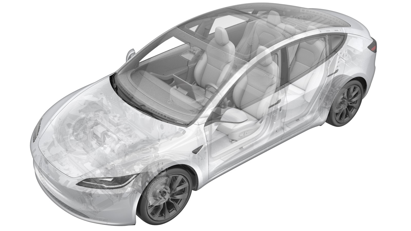 Correction code
16300501002
FRT
1.38
NOTE: Unless
otherwise explicitly stated in the procedure, the correction code and its
associated FRT reflect all of the work required to perform this procedure,
including the linked procedures. Do not stack correction
codes unless explicitly told to do so.
NOTE: See Flat Rate Times to
learn more about FRTs and how they are created.
NOTE: See Personal Protection to make
sure you are wearing proper PPE when performing the procedure below.
NOTE: See Ergonomic Precautions for safe and healthy
working practices.
Equipment:
- 1057602-00-A Ratchet, 1/4" Sq Dr, HV Insulated
- 1057604-00-A Skt, 1/4" Sq Dr, 8mm, HV Insulated
- 1131071-00-A Dummy Disconnect, Pyro, Safety
- 1108272-00-B Cap, Logic Conn, Inv, 3DU
- 1076927-00-A Resistance meter, microohm, Hioki RM 3548
Only
technicians who have completed all required certification courses are permitted to
perform this procedure. Tesla recommends third party service provider technicians
undergo equivalent training before performing this procedure. For more information on
Tesla Technician requirements, or descriptions of the subject matter for third parties,
see HV Certification Requirements. Proper personal protective equipment (PPE) and insulating HV
gloves with a minimum rating of class 0 (1000V) must
be worn at all times a high voltage cable, busbar, or fitting is handled. Refer to Tech Note TN-15-92-003, High Voltage Awareness
Care Points
for additional safety
information.
Remove
-
Perform the Vehicle HV Disablement
Procedure. See Vehicle HV Disablement Procedure.
NoteAfter verifying there is no HV voltage, reinstall the removed parts but Do not reconnect the LV power.
- Remove the 2nd row lower seat cushion. See Seat Cushion - 2nd Row (Remove and Replace).
-
Remove the ancillary bay cover. See
Ancillary Bay Cover (Remove and Install).
WarningHV insulating gloves and leather glove protectors must be worn throughout the remainder of this procedure. Do not remove gloves or protectors until otherwise noted.
-
Install the logic connector cap to the high voltage controller connector.
-
Inspect the ancillary bay for missing insulators.
NoteInstall the service insulator kit before proceeding with the following steps.
- Remove the pyrotechnic battery disconnect. See Pyro Disconnect - HV Battery (Remove and Replace).
-
Use rubber bands to secure the high voltage controller to the vehicle.
-
Remove the insulators (x2) from the
fuse and bolts.
-
Remove and discard the nuts (x2) that
attach PCS2 output fuse to the ancillary bay bus, and then remove the fuse.
TipUse of the following tool(s) is recommended:
- Insulated 8 mm socket
-
Remove and discard the nut that
attaches the negative output harness to negative HV battery DC link busbar.
TipUse of the following tool(s) is recommended:
- Insulated 8 mm socket
-
Remove and discard the nuts (x2) that
attach the A/C compressor fuse to the ancillary bay bus, and then remove the fuse.
TipUse of the following tool(s) is recommended:
- Insulated 8 mm socket
-
Remove and discard the nut that
attaches the ancillary positive busbar bracket to the positive HV battery DC link
busbar, and then remove the bracket.
TipUse of the following tool(s) is recommended:
- Insulated 8 mm socket
-
Disconnect the HV DC harness connector
from the PCS2 Lite by pulling the locking tab upward.
NoteMay need a plastic trim tool to help lift the connector upward.
-
Remove the bolt that attaches the RH
ancillary bay bus cover to the body.
TipUse of the following tool(s) is recommended:
- Insulated Torx T25 bit
-
With assistance, carefully lift up the
DC link busbar cover.
Note1x clip. Be careful not to damage cover when lifting.
-
Remove the PCS2 lite HV DC harness
from the ancillary bay.
NoteIt is not allowed to damage the insulation layer of the harness. If it is damaged, replace the harness.
Install
-
Install the PCS2 lite HV DC harness to
the ancillary bay.
Note3x harness slots, 1x hook, 2x studsCAUTIONIt is not allowed to damage the insulation layer of the harness. If necessary, use a HV insulated 90 degree hook to assist.CAUTIONMake sure that harness is not pinched.NoteAfter the harness is properly positioned, install the harness terminals onto the bolt studs.
-
Carefully lower the DC link busbar
cover into position.
Note1x clip
-
Install the bolt that attaches the RH
ancillary bay bus cover to the body.
 3 Nm (2.2 lbs-ft)TipUse of the following tool(s) is recommended:
- Insulated Torx T25 bit
-
Connect the HV DC harness connector to
the PCS2 Lite by pushing it downward, then pressing the locking tab down to secure
it.
-
Install a new nut that attaches the
negative output harness to negative HV battery DC link busbar.4.5 Nm (3.3 lbs-ft)NoteMark the nut with a paint pen after installation.TipUse of the following tool(s) is recommended:
- Insulated 8 mm socket
-
Perform a zero adjust of the Hioki
resistance meter in preparation to measure resistances later in this procedure.
WarningHV insulating gloves and leather glove protectors must be worn throughout the remainder of this procedure. Do not remove gloves or protectors until otherwise noted.
-
Use the Hioki resistance meter to
measure the resistance at the negative output harness terminal and the negative HV
battery DC link busbar.
NoteThe maximum acceptable resistance is 55μΩ or less.
-
Install a new nut that attaches the ancillary positive busbar bracket to the positive
HV battery DC link busbar.4.5 Nm (3.3 lbs-ft)NoteMark the nut with a paint pen after installation.TipUse of the following tool(s) is recommended:
- Insulated 8 mm socket
-
Use the Hioki resistance meter to
measure the resistance at the ancillary positive busbar bracket to positive HV battery
DC link busbar.
NoteThe maximum acceptable resistance is 60μΩ or less.
-
Install new nuts (x2) that attach PCS2
output fuse to the ancillary bay bus.4.5 Nm (3.3 lbs-ft)NoteMark the nut with a paint pen after installation.TipUse of the following tool(s) is recommended:
- Insulated 8 mm socket
-
Use the Hioki resistance meter to
measure the resistance at the PCS fuse input joint.
NoteThe maximum acceptable resistance is 145μΩ or less.
-
Use the Hioki resistance meter to
measure the resistance at the PCS fuse output joint.
NoteThe maximum acceptable resistance is 105μΩ or less.
-
Install new nuts (x2) that attach the
A/C compressor fuse to the ancillary bay bus.4.5 Nm (3.3 lbs-ft)NoteMark the nut with a paint pen after installation.TipUse of the following tool(s) is recommended:
- Insulated 8 mm socket
-
Use the Hioki resistance meter to
measure the resistance at the compressor fuse input joint.
NoteThe maximum acceptable resistance is 145μΩ or less.
-
Use the Hioki resistance meter to
measure the resistance at the compressor fuse output joint.
NoteThe maximum acceptable resistance is 105μΩ or less.
-
Release the rubber bands, and then
position the high voltage controller back to its original position.
-
Install the insulators (x2) onto the
fuse and bolts.
- Measure the voltage across the pyrotechninc battery disconnect mount points, and then install the pyrotechnic battery disconnect. See Pyro Disconnect - HV Battery (Remove and Replace).
-
Remove the service insulator
kit.
-
Remove the logic connector cap from the high voltage controller connector.
-
Install the ancillary bay cover. See
Ancillary Bay Cover (Remove and Install).
NoteBefore installing the ancillary bay cover, inspect the ancillary bay cover seal and confirm there is no visual damage. If the seal is torn and/or delaminated, replace the ancillary bay cover.
- Install the 2nd row lower seat cushion. See Seat Cushion - 2nd Row (Remove and Replace).
- Connect the LV power. See LV Power (Disconnect and Connect) (Modify).