Air Line Front Bundle (Remove and Replace)
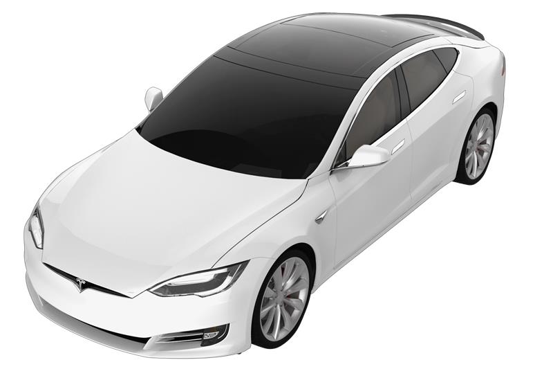 Correction code
31104012
FRT
0.66
NOTE: Unless
otherwise explicitly stated in the procedure, the correction code and its
associated FRT reflect all of the work required to perform this procedure,
including the linked procedures. Do not stack correction
codes unless explicitly told to do so.
NOTE: See Flat Rate Times to
learn more about FRTs and how they are created.
NOTE: See Personal Protection to make
sure you are wearing proper PPE when performing the procedure below.
NOTE: See Ergonomic Precautions for safe and healthy
working practices.
- 2026-11-11: Released new procedure.
-
Raise and support vehicle
NoteSet air suspension to "Jack Mode", Position lift arm pads on vehicle jack pads
-
Open LH front door
-
Connect laptop to vehicle with a tethered Ethernet connection via Toolbox 3
Note1x connector, 2x clips, Newer models will access connector below MCU with cubby removed, Older models will access port at LH side of IP with end cap removedOpen Toolbox 3 website and establish connection to vehicle: https://toolbox.teslamotors.com, Select connection status icon at top right corner and select Connect Locally (icon will turn green when vehicle is connected), Local connection will enable service mode plus on display
-
Open Tesla Air Suspension service panel
NotePanels > Air Suspension > ''Tesla Air Suspension''
-
Place Air Suspension into Service Mode
NoteSelect ''ENTER'' in ''TAS Service Mode'' sub-menu, Drive rails must be on for function to complete
-
Deflate the LH Front Air Strut
NoteSelect "Deflating" under Action, then "Front Left" under Corner, then hit the "Play" button, Drive rails must be on for function to complete
-
Deflate the RH front air strut
NoteSelect "Deflating" under Action, then "Front Left" under Corner, then hit the "Play" button, Drive rails must be on for function to complete
-
Deflate ''Reservoir''
NoteSelect ''Reservoir'' then select "Deflate" under Inflate / Deflate tab
-
Open hood
NoteVia Controls > Front Trunk
-
Remove rear underhood apron
Note8x clips
-
Remove RH underhood apron
Note9x clips
-
Remove LH underhood apron
Note9x clips, (*Use this step for Model S Refresh procedures)
-
Release primary and secondary drain tubes from cabin intake duct assembly
Note2x hoses
-
Release cabin intake duct assembly from cowl panel
Note3x push clips
-
Remove cabin intake duct assembly
Note2x tabs, one on each side
-
Raise vehicle partially and lower onto locks
NoteSet vehicle to comfortable working height, Make sure there's an audible click of locks on both sides before lowering, otherwise vehicle may tilt to side
-
Release air line fitting from LH air spring module
Note1x nut, 10mm, 2 Nm, Once air leak can be heard, stop turning until all air released
-
Remove compression fitting from RH air line
NoteSlide threaded section back, Slide compression sleeve off, Then slide threaded section off of air line, Discard after removal
-
Release air line fitting from RH front air spring module
Note1x nut, 10mm, 2 Nm, Once air leak can be heard, stop turning until all air released
-
Remove compression fitting from RH air line
NoteSlide threaded section back, Slide compression sleeve off, Then slide threaded section off of air line, Discard after removal
-
Remove the air line from air reservoir
Note1x nut, 12mm, 5 Nm, Use a 13mm wrench to hold the reservoir nut to release the 12mm nut on air line
-
Remove compression fitting from air lines
NoteSlide threaded section back, slide compression sleeve then threaded section off of air line, Discard fittings after removal
-
Remove air lines into air compressor
Note3x VOSS line fittings,
-
Remove air line assembly from retainers
Note3x retainer clips
-
Install new air line bundle into retainer clips
Note3x retainer clips
-
Remove plug and install air line into RH air spring module
NotePress hose into fitting until mark aligns with top of fitting, Verify line is properly secured by performing push and pull test
-
Remove plug and install air line into LH air spring module
Note1x VOSS fitting, Press hose into fitting until mark aligns with top of fitting, Verify line is properly secured by performing push and pull test
-
Install air line into air suspension reservoir
NoteRemove the white plugs if not already done, Fully insert air line into fitting until it goes no further, It should sit between the two white marks on the air line, Verify lines is properly secured by performing push and pull test
-
Install air lines into air compressor
Note3x VOSS fittings, Remove plastic plugs from new fittings before pushing lines in, Gently pull on air suspension lines to make sure lines are secured to compressor.
-
Remove cap from valve on air suspension reservoir
Note1x cap
-
Attach nitrogen tank adapter to reservoir
-
Open pressure regulator valve on nitrogen tank to release line pressure in lines
NoteOpen regulator valve to adjust pressure to 19-21 bar (275-305 psi), Open the valve slowly as gas pressure rises
-
Open lever on hose adapter to fill reservoir
NoteSupplying Nitrogen automatically fills the reservoir. Nitrogen supply begins filling the reservoir up to 275 psi or 19 bar. Give it some time to settle pressure equally between set Nitrogen set pressure and vehicle reservoir
-
Verify the correct Gallery Pressure
NoteSpring pressure during fill should be 8-10 bar, Pressure must be met or the Toolbox program will show an error, Adjust using nitrogen tank regulator if necessary
-
Fill the LH front strut
NoteSelect "Filling" under Action, then "Front Left" under Corner, then hit the "Play" button, Drive rails must be on for function to complete
-
Fill the RH front strut
NoteSelect "Filling" under Action, then "Front Right" under Corner, then hit the "Play" button, Drive rails must be on for function to complete
-
Close main valve on nitrogen tank
-
Close lever on hose adapter to fill reservoir
-
Close pressure regulator valve on nitrogen tank
-
Disconnect nitrogen tank hose from reservoir
-
Install cap onto reservoir valve
Note1x cap
-
Open Tesla Air Suspension service panel
NotePanels > Air Suspension > ''Tesla Air Suspension''
-
Take Air Suspension out of Service Mode
NoteSelect ''EXIT'' in ''TAS Service Mode'' sub-menu, Drive rails must be on for function to complete
-
Disconnect Toolbox from vehicle and install cubby
Note1x connector, 2x clips, Ensure diagnostic cables are tucked into appropriate position then engage cubby
-
Install cabin intake duct assembly
Note2x tabs, One on each side
-
Secure cabin intake duct assembly to cowl panel
Note3x push clips
-
Secure primary and secondary drain tubes to cabin intake duct assembly
Note2x hoses
-
Install RH underhood apron
Note9x clips
-
Install LH underhood apron
Note9x clips
-
Install rear underhood apron
Note8x clips
-
Close hood
NotePress firmly in green highlighted areas (see image), Damage may result from pressure elsewhere on hood
- Run ODIN routine
-
Verify operation of air suspension
NoteCycle ride height via touchscreen, Controls > Suspension > ''Low'' - ''Very High'', All doors must be closed to allow ride height to cycle, Set suspension back to ''Standard'' after verification
-
Close LH front door
-
Perform test drive
NotePer current FRT 00040100 (0.3)