2023-05-24
Pin Carrier - Charge Port (Remove and Replace)
Correction code 44016102
- 2023-05-24: Updated procedure to use Charge Port Voltage Check, and not Vehicle Electrical Isolation Procedure.
- 2023-04-18: Fixed incorrect hyperlink to Vehicle Electrical Isolation Procedure.
Removal
- Open the LH front door and lower the window.
- Open the liftgate.
- Open the charge port door.
- Disconnect 12V power. See Disconnect 12V Power.
- Perform the charge port voltage check. See Charge Port Voltage Check.
- Remove the LH rear trunk side trim, see Trim - Rear Trunk - Side - LH (Remove and Replace).
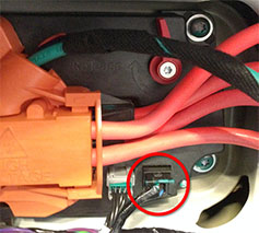
- Release the 12V harness connection from the charge port.
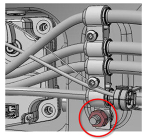
- Remove the grounding bracket by releasing the nut that secures it to the body (torque 6 Nm).
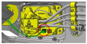
- Disconnect the harness that connects the taillight to the charge port.
-
Remove the charge port cover.
-
Remove the bolts (x3) that attach the
HV harness to the charge port in the order shown.
-
Remove the HV harness from the charge
port assembly.
-
Remove the screws (x2) that attach the
pin carrier to the pin carrier cap.
-
Partially separate the pin carrier
from the pin carrier cap near the screw holes.
CAUTIONAvoid pinching or damaging any wires inside the charge port.
-
Fully separate the pin carrier from
the pin carrier cap near the screw holes.
NotePosition a trim tool below the 2 clear tabs, then separate the pin carrier from the pin carrier cap until the 2 rear tabs disengage.
-
Remove the screw that attaches the pin
housing to the pin carrier.
NoteIf the screw is corroded, discard the screw and install a new one during reassembly.
-
Move the pin housing away from the pin
carrier.
-
Release the 3 pins from the pin
carrier.
NotePlace a shop cloth on top of the trunk floor insulation pad, and then push the pin carrier down onto the shop cloth to release the 3 pins from the pin carrier. Discard the pin carrier.
-
Inspect the pin carrier cap and pin
holder for cracks or damage.
NoteIf the pin carrier cap or the pin holder was damaged during disassembly, replace the pin carrier cap and/or the pin holder (3x screws, 1 Nm).
-
Remove and discard the O-rings from
all 7 pins.
NoteUse a pick to remove the O-rings from the pins.CAUTIONHold the pins by the pin body, do not hold the pins by the wires.
Installation
- Clean all pins with an IPA wipe and allow to dry for at least 1 minute.
-
Install new O-rings on the 7
pins.
CAUTIONSlide the new O-rings on by hand. Install the smaller O-rings on the 2 data pins, and the larger O-rings on the rest of the pins.
-
Install a new O-ring onto the new pin
carrier.
-
Insert a new smaller O-ring on the pin
carrier screw bore.
-
Install the screw (torque 0.5 Nm) that
attaches the pin housing to the pin carrier.
-
Apply Krytox lubricant onto the pin O-rings (x3). Do not apply Krytox lubricant on
the pins.
NoteUse a clean shop cloth to remove any lubricant from the pins.
-
Insert the 2 data pins and the ground
pin into the pin carrier ports: partially insert the 2 data pins and the ground pin into
the pin carrier ports, and then use a small flat screwdriver or similar tool to fully
insert each pin into the pin carrier.
NoteInserting the pins into the pin carrier requires significant force.
-
Make sure that the pins are fully
inserted into the pin carrier.
NoteThe pins must be inserted at least 2 mm past the edge of the pin bore.
-
Route the charge port wiring harness
in front of the HV cables.
-
Apply Krytox lubricant onto the remaining pin O-rings (x4). Do not apply Krytox
lubricant on the pins.
NoteUse a clean shop cloth to remove any lubricant from the pins.
-
Slide the pins (x4) into the pin
carrier.
-
Install the screws (x2) that attach
the pin carrier to the pin carrier cap (torque 0.6 Nm).
NoteIf the screws are corroded, discard them and install new ones.
-
Install the bolts (x3) that attach the
HV harness to the charge port assembly (torque 5 Nm).
NoteFirst hand tighten the bolts, then torque the bolts in the order shown.
- Make sure that the vehicle's charging system operates appropriately.