2025-04-17
Charge Port (Type 2, Non-Motorized Charge Port) (Remove and Replace)
FRT No: 44012102
Note
This procedure describes how to remove
and install the 3 phase charge port. If the vehicle is equipped with a single phase
charge port, refer to procedure Charge Port (NACS, Non-Motorized) (Remove and Replace) or Charge Port - Motorized (NACS) (Remove and Replace).
Warning
Only technicians who have been
trained in High Voltage Awareness and have completed all required certification
courses (if applicable) are permitted to perform this procedure. Proper personal
protective equipment (PPE) and insulating HV gloves with a minimum rating of
class 0 (1000V) must be worn any time a high voltage cable is handled. Refer to
Tech Note TN-15-92-003, "High Voltage Awareness Care Points"
for additional safety information.
- 2023-05-24: Updated procedure to use Charge Port Voltage Check.
Removal
- Open the charge port.
- Disconnect 12V power. See Disconnect 12V Power.
- Perform the charge port voltage check. See Charge Port Voltage Check.
- Remove the LH trunk trim. See Trim - Rear Trunk - Side - LH (Remove and Replace).
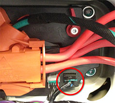
- Release the 12V harness connection from the charge port.
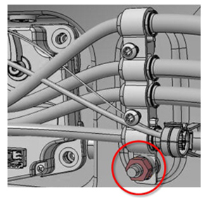
- Remove the grounding bracket by releasing the nut that secures it to the body (torque 6 Nm).
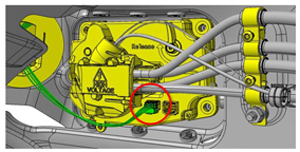
- Disconnect the harness that connects the taillight to the charge port.
-
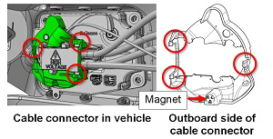
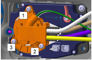
Remove the cover from the cable
connector by using a trim tool or similar non-conductive tool to bend the 3 tabs
that secure the cover to the cable connector.
NoteThe locations of the tabs are marked by arrows on the face of the cover.CAUTIONDo not lose or damage the magnet on the outboard side of the cable connector.
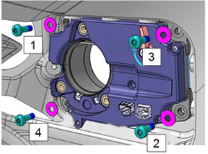
- Remove the 3 bolts that secure the cable connector to the charge port in the order shown (torque 4 Nm). Remove the cable connector.
- Remove the LH taillight assembly. See Taillight Assembly - LH (Remove and Replace).
- Remove the bolts in the order shown (torque 3 Nm). Remove the charge port.
Installation
-
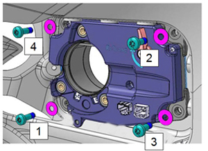
When securing the charge port to
the body, install all four bolts loosely, then tighten them in the order
shown.
CAUTIONDo not over-tighten the bolts during installation to prevent water leaks inside the trunk area.
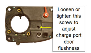
- Before installing the cable connector, close the charge port door and verify that it is 0-2 mm underflush to the body. If necessary, turn the screw to adjust the magnet that secures the charge port door.
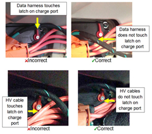
- When reinstalling the cable connector, ensure that the HV cables and data harness do not touch or interfere with the latch on the inside of the charge port.
- When securing the cable connector to the charge port, loosely install all 3 bolts, then tighten them in the order shown.
- Update the vehicle firmware. See Firmware Update.
- Connect a laptop to the diagnostic port of the vehicle, and then use Toolbox 3 to locally connect to the vehicle. See Toolbox 3 (Connect and Disconnect).
- Unlock the vehicle gateway for diagnostic communication. See Gateway Unlock.
-
Perform Charge Port Latch
Calibration.
- For Intel/Tegra vehicles: In Toolbox 3, click the Actions tab, type "Charge Port Latch Calibration" into the search field, click PROC_CP_X_LATCH-CALIBRATIONvia Service Mode:High Voltage ➜ Charging ➜ Charge Port Latch Calibrationvia Toolbox:(link), click Run, and allow the routine to complete.
- For Intel vehicles only: On the touchscreen, tap the Service Mode "wrench" (at the bottom of the touchscreen UI), and then tap , and allow the routine to complete.
-
Perform Charge Port Door
Calibration.
- For Intel/Tegra vehicles: In Toolbox 3, click the Actions tab, type "Charge Port Door Calibration" into the search field, click PROC_CP_X_DOOR-SENSOR-CALIBRATIONvia Service Mode:High Voltage ➜ Charging ➜ Charge Port Door Calibrationvia Toolbox:(link), click Run, and allow the routine to complete.
- For Intel vehicles only: On the touchscreen, tap the Service Mode "wrench" (at the bottom of the touchscreen UI), and then tap , and allow the routine to complete.
- Perform a charging session and make sure that charging proceeds as intended.