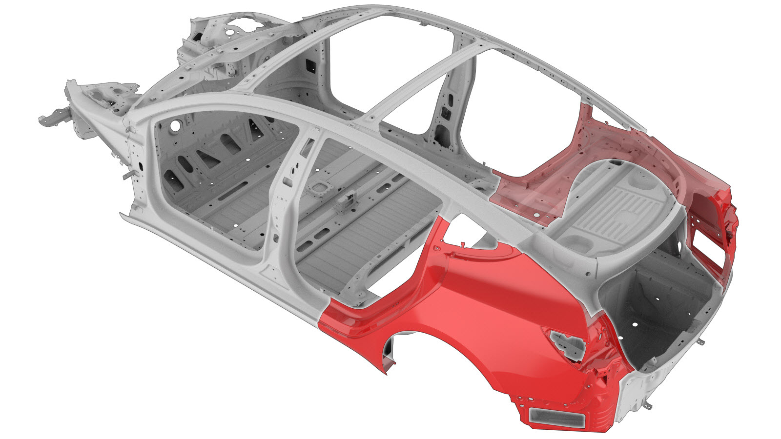
围板外件总成(不带顶部槽)
 校正代码:
10100121802
10100140402
注意:除非本程序中有明确规定,否则上述校正代码涵盖执行本程序(包括关联碰撞维修程序)所需的所有碰撞维修工作。除非明确要求,否则请勿堆叠碰撞维修校正代码。添加执行此程序所需的任何关联机械程序。
维修信息
- 在开始本程序之前,请查看所有碰撞维修一般实践和安全文档并佩戴适当的 PPE(个人防护装备)。
- 不使用车架工作台也可完成此程序。
- 只要使用本文档中 围板外件总成区块说明 部分指定的参考切割线,即可更换车身侧外件总成的任何一个区块或多个区块的任意组合。
使用本文档
- 围板外件总成区块说明 阐述必要时切割围板外件总成(或子总成)的位置和方法,用于更换围板外件总成的损坏区域,或者为车辆结构底部零件留出操作空间。参考区块说明判定在维修时根据需要成功切割车身侧外件总成的位置。注只要使用本文档标示的参考切割位置,即可逐个更换或组合更换围板外件总成的各个区块。注对螺栓孔位置的测量应以参考孔的中心为起点,除非区块说明中有不同的表述。
- 本文档的 维修程序 部分提供了更换整个围板外件总成所需的信息。如欲更换围板外件的各个区块,而非整个围板外件总成,请参考各步骤的相关部分来确定需要哪些零件和紧固件,以及完成维修需要执行哪些步骤。
零件清单
| 数量 | 描述 | 图片/备注 |
|---|---|---|
| 1 | ASSEMBLY, REAR QUARTER OUTER(后围外件总成) | |
| 10 | 结构型灯笼铆钉,6.5 mm | |
| 12 LH 或 11 RH | 流型铆钉 S18 |
如需订购零件,请参阅零件目录,输入需维修车辆 VIN,查找车辆正确零件(以及零件号)。或者,也可以在零件目录中搜索,查找车辆专用零件。
围板外件总成区块说明
| 围板外件总成分割 | ||
|---|---|---|
| 围板外件总成属于单个总成,可整体更换,也可不更换整个围板外件总成,而是参考本文档所述的切割线,分区域更换整个围板外件总成的各个部分。 | ||
|
|
| 围板外件区块说明 | 接头说明 |
|---|---|
|
围板外壳区块 切割线 警告 切勿在底部后轮罩加固件的正上方切割车身侧外件面板。 参考线/点
注 从孔的侧面测量,如图所示。 GMA 焊缝 注 本区块对接接头的相邻面板之间的间隙应尽可能小,以最大限度提高连接强度。 注 使用结构型粘合剂填充焊缝中的间隙,并在焊接后密封任何外露的焊缝。 |
|
|
转向部分区块 切割线 参考线/点
注 从孔的侧面测量,如图所示。 警告 切勿在底部铝制组件的正上方切割钢制车身侧外件面板。底部组件(红色突出显示部分)包括后轮罩加固件和后轮拱总成。 GMA 焊缝 注 本区块对接接头的相邻面板之间的间隙应尽可能小,以最大限度提高连接强度。 注 焊接后密封所有外露的焊缝。 |
|
|
后门槛区块 切割线 参考线/点
GMA 焊缝 注 可在指定切割线每一侧的 50 毫米范围内进行切割。 注 本区块对接接头的相邻面板之间的间隙应尽可能小,以最大限度提高连接强度。 注 焊接后密封所有外露的焊缝。 |
|
|
后车顶纵梁区块 注 如果维修区域包含车顶纵梁的任一部分,请勿使用此程序;可参阅车身侧外件。 |
维修程序
-
从后围外件总成维修零件上拆下顶部槽。
或 原厂点焊焊缝或 钻透原厂点焊焊缝注钻除点焊焊缝时,请确保使用的钻头能钻出一个大小合适的孔,以便用紧固件代替点焊焊缝。
-
拆卸原装部件。
或 原厂点焊焊缝注不要去除用黄色圆圈突出显示区域内的点焊焊缝。
或 原厂 SPR
或 钻透原厂点焊焊缝注钻除点焊焊缝时,请确保使用的钻头能钻出一个大小合适的孔,以便用紧固件代替点焊焊缝。 -
分开轮拱法兰。
-
准备安装。
- 在车辆接合面以及新部件上涂抹结构型粘合剂。
-
安装新部件。
注仅限使用结构型粘合剂固定车身侧外件底部法兰。
- 折叠轮拱法兰。
-
执行电阻点焊。
或 安装点焊焊缝警告未遵守包括使用个人防护装备在内的任何焊接安全注意事项,可能导致严重的人身伤害或财产损失。只有已完成 Tesla 认可的焊接培训课程的维修技师才有权在 Tesla 车辆上焊接结构组件。警告切勿在执行车辆电气绝缘程序前焊接 Tesla 车辆(请参阅车辆专用维修手册,了解有关车辆电气绝缘程序的更多信息)。在具有通电高压或低压系统的 Tesla 车辆上进行焊接可能会损坏车辆部件。
-
执行 GMA 焊接。
或 钢塞焊焊缝
GMA 焊缝
警告未遵守包括使用个人防护装备在内的任何焊接安全注意事项,可能导致严重的人身伤害或财产损失。只有已完成 Tesla 认可的焊接培训课程的维修技师才有权在 Tesla 车辆上焊接结构组件。警告为保持车辆碰撞完整性,在采用 GMA 焊接法焊接 Tesla 车辆时,仅允许使用经批准的焊丝和 GMA 焊接器。请参阅已批准的气体保护金属极弧 (GMA) 焊接器和焊丝了解有关经批准的 GMA 焊接器和焊丝的信息。警告切勿在执行车辆电气绝缘程序前焊接 Tesla 车辆(请参阅车辆专用维修手册,了解有关车辆电气绝缘程序的更多信息)。在具有通电高压或低压系统的 Tesla 车辆上进行焊接可能会损坏车辆部件。注进行 GMA 焊接之前,使用规格和类型相同的材料执行焊接测试,以确保焊接设备的设置能保证满意的焊接效果。 -
用结构型粘合剂填充所示接缝。
-
对于红色圆圈标示的塞焊焊缝,密封在该塞焊焊缝背面钻孔后留下的孔。
-
折叠轮拱法兰。
- 如果原充电端口外壳设有接地线或线束连接点,请在新充电端口外壳上为防松螺母或固定夹钻一个孔。(请参阅充电接口外壳总成程序,了解有关孔洞尺寸和位置的信息。)
- 执行任何必要的维修后操作。