2026-08-05

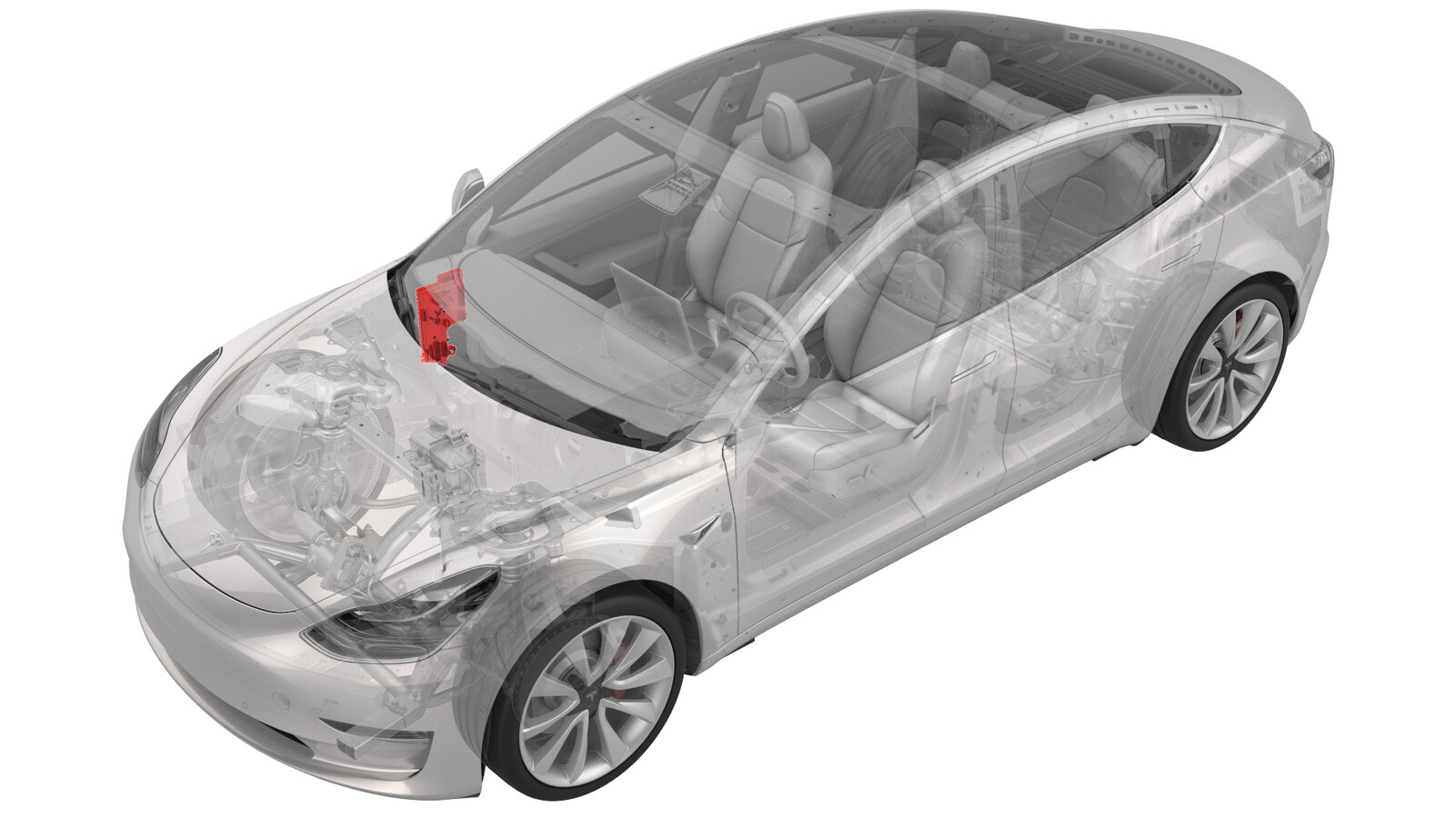
模块 - 车身控制器 - RH(左侧驾驶)(带加热泵款)(拆卸和更换)

校正代码 17152212 0.96 注意:除非本程序中另有明确规定,否则上述校正代码和 FRT 反映的是执行本程序(包括关联程序)所需的所有工作。除非明确要求,否则请勿堆叠校正代码。 注意:请参阅平均维修工时,深入了解 FRT 及其创建方式。 注意:请参阅人员保护,确保在执行以下程序时穿戴适当的个人防护装备 (PPE)。注意:请参阅查看安全健康的作业规程。

  • 2026-08-05: Removed the Service Mode Plus "Mid-Voltage" direction.
  • 2025-03-10: Updated post-replacement routine.
  • 2023-07-14: Updated procedure to latest GSD validation for M3.

拆卸

  1. Open the front doors and lower the windows.
  2. Remove the rear underhood apron. See 前备箱挡板 - 后部(拆卸和更换).
  3. Disconnect 12V power. See 12V/低压电源(断开和连接).
  4. Remove the LH instrument panel end cap. See 端盖 - 仪表板 - 左侧(拆卸和更换).
  5. Remove the LH air wave end cap. See #GUID-B0D53054-F197-4059-AA3C-A737928DE1DD.
  6. Repeat steps 4 and 5 for the RH side of the vehicle.
  7. Remove the main instrument panel decor trim. See .
  8. Remove the RH middle A-pillar trim. See 饰板 - A 柱 - 中部 - 左侧(拆卸和更换).
  9. Remove the RH lower A-pillar trim. See 饰板 - A 柱 - 下 - 左侧(拆卸和更换).
  10. Remove the passenger footwell cover. See #GUID-B1021D27-F10C-490E-B5DE-FC92351E561D.
  11. Remove the front passenger knee airbag (if equipped). See .
  12. Remove the glove box. See #GUID-44E5E30F-19DC-4B8A-8AEA-85200FE5896B or .
  13. Remove the RH front floor mat.
  14. Remove the RH center console side panel carpet. See 侧板 - 中控台 - 左侧(拆卸和更换).
  15. Release the clips (x3) that attach the RH front carpet to the body at the RH A-pillar.
  16. Fold back the RH front carpet.
    Informational PurposesAn informational icon, calling your attention
    Note
    Release the seat harness from the clips at the RH door sill to allow the carpet to further fold back.
  17. Remove the nuts (x2) that attach the RH side carpet locator bracket.
    Informational PurposesAn informational icon, calling your attention
    Note
    Later vehicles may use 2x push clips instead.
  18. Release the connector lock, and then disconnect the J7 door electrical connector from the RH body controller module.
  19. Release the connector lock, and then disconnect the J9 front passenger seat electrical connector from the RH body controller module.
  20. Disconnect the J10 instrument panel electrical connector from the RH body controller module.
  21. Disconnect the J11 HVAC electrical connector from the RH body controller module.
  22. Release the connector lock, and then disconnect the J1 power electrical connector from the RH body controller module.
  23. Release the connector lock, and then disconnect the J4 body electrical connector from the RH body controller module.
  24. Disconnect the RH body harness connector.
  25. Release the harness clips below the IP carrier.
  26. Disconnect the J6 underhood storage unit electrical connector from the RH body controller module.
  27. Release the connector lock, and then disconnect the J2 body electrical connector from the RH body controller module.
  28. Disconnect the J12 body electrical connector from the RH body controller module.
  29. Disconnect the J5 body electrical connector from the RH body controller module.
  30. Disconnect the connectors from the harness clip at the RH lower A-pillar area.
  31. Remove the RH body harness clip from the lower A-pillar area.
  32. Remove the RH body harness clips from the RH body controller module.
  33. Move the RH body harness away from the RH body controller module.
  34. Remove and discard the nyloc nut that attaches the RH body controller module to the vehicle.
    Informational PurposesAn informational icon, calling your attention
    Note
    推荐使用以下工具
  35. Slide the RH body controller module upwards to release the W clip, maneuver the RH body controller module out from under the IP, and then remove the RH body controller module from the vehicle.

安装

  1. Maneuver RH body controller module into position under the IP carrier, align the W clip with the body cut out, and then slide down the RH body controller module to secure it.
  2. Install a new nyloc nut that attaches the RH body controller module to the vehicle (torque 6 Nm).
    Informational PurposesAn informational icon, calling your attention
    Note
    推荐使用以下工具
  3. Move the RH body harness towards the RH body controller module.
  4. Install the RH body harness clips to the RH body controller module.
  5. Install the RH body harness clip to the RH lower A-pillar area.
  6. Connect the connectors at the harness clip at the RH lower A-pillar area.
  7. Connect the J5 body electrical connector to the RH body controller module.
  8. Connect the J12 body electrical connector to the RH body controller module.
  9. Connect the J2 body electrical connector to the RH body controller module: fully seat the connector, and then engage the lock.
  10. Connect the J6 underhood storage unit electrical connector to the RH body controller module.
  11. Connect the J1 power electrical connector to the RH body controller module.
  12. Connect the J4 body electrical connector to the RH body controller module.
  13. Connect the connector of the RH body harness.
  14. Connect the J11 HVAC electrical connector to the RH body controller module.
  15. Connect the J10 instrument panel electrical connector to the RH body controller module.
  16. Connect the J9 front passenger seat electrical connector to the RH body controller module.
  17. Connect the J7 door electrical connector to the RH body controller module.
  18. Install the harness clips below the IP carrier.
  19. Install the nuts (x2) that attach the RH side carpet locator bracket (torque 2.5 Nm).
    Informational PurposesAn informational icon, calling your attention
    Note
    Later vehicles may use push clips instead of nuts.
  20. Unfold the RH front carpet, and then reinstall the harness into the clips at the RH door sill.
  21. Install the clips (x3) that attach the RH front carpet to the body.
  22. Install the RH center console side panel carpet. See 侧板 - 中控台 - 左侧(拆卸和更换).
  23. Install the RH front floor mat.
  24. Install the glove box. See #GUID-44E5E30F-19DC-4B8A-8AEA-85200FE5896B or .
  25. Install the front passenger knee airbag (if equipped). See .
  26. Install the passenger footwell cover. See #GUID-B1021D27-F10C-490E-B5DE-FC92351E561D.
  27. Install the RH lower A-pillar trim. See 饰板 - A 柱 - 下 - 左侧(拆卸和更换).
  28. Install the RH middle A-pillar trim. See 饰板 - A 柱 - 中部 - 左侧(拆卸和更换).
  29. Install the main instrument panel decor trim. See .
  30. Install the RH air wave end cap. See #GUID-B0D53054-F197-4059-AA3C-A737928DE1DD.
  31. Install the RH instrument panel end cap. See 端盖 - 仪表板 - 左侧(拆卸和更换).
  32. Repeat steps 30 and 31 for the LH side of the vehicle.
  33. Connect 12V/LV power. See 12V/低压电源(断开和连接).
  34. Install the rear underhood apron. See 前备箱挡板 - 后部(拆卸和更换).
  35. 通过“维护模式”或 Toolbox 执行以下例行程序(请参阅): UPDATE_CAN-REDEPLOYvia Service Mode Plus:
    • Drive Inverter Replacement ➜ Drive Inverter DIRE1L Replacement ➜ CAN Redeploy
    • Drive Inverter Replacement ➜ Drive Inverter DIRE1R Replacement ➜ CAN Redeploy
    • Drive Inverter Replacement ➜ Drive Inverter DIRE2 Replacement ➜ CAN Redeploy
    • Drive Inverter ➜ Front Drive Inverter Replacement ➜ CAN Redeploy
    • Drive Inverter ➜ Rear Drive Inverter Replacement ➜ CAN Redeploy
    • Drive Inverter ➜ Rear Left Drive Inverter Replacement ➜ CAN Redeploy
    • Drive Inverter ➜ Rear Right Drive Inverter Replacement ➜ CAN Redeploy
    • Drive Unit ➜ Front Drive Unit Replacement ➜ CAN Redeploy
    • Drive Unit ➜ Rear Drive Unit Replacement ➜ CAN Redeploy
    • Thermal ➜ HVAC ➜ CAN Redeploy
    • chassis ➜ DPB Post Replacement ➜ CAN Redeploy
    • chassis ➜ ESP Post Replacement ➜ CAN Redeploy
    • chassis ➜ IDB Post Replacement ➜ CAN Redeploy
    • chassis ➜ RCU Post Replacement ➜ CAN Redeploy
    • chassis ➜ ESP Replacement Panel ➜ CAN Redeploy
    • chassis ➜ IBST Replacement Panel ➜ CAN Redeploy
    via Toolbox:(link)
  36. Once firmware redeploy is complete, verify on the center display that the release notes are present.
  37. Sit in the driver seat and close the LH front door.
  38. 通过“维护模式”或 Toolbox 执行以下例行程序(请参阅): PROC_CONTROLLER_RIGHT_POST-REPLACEMENT-PROCEDUREvia Service Mode Plus:low-voltage ➜ Right Controller Post Replacement ➜ Right Controller Post Replacement Procedurevia Toolbox:(link)
    Informational PurposesAn informational icon, calling your attention
    Note
    Keep the front passenger seat clear of any objects during calibration.
  39. Close the front doors and raise the windows.