2026-08-09
HV Header - Inverter - Rear Drive Unit (Remove and Replace)
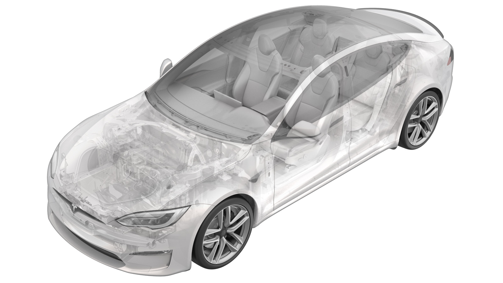 Correction code
40206302
0.90
NOTE: Unless otherwise explicitly
stated in the procedure, the correction code and its associated FRT reflect all of the
work required to perform this procedure, including the linked procedures. Do not stack correction codes unless
explicitly told to do so.
NOTE: See Flat Rate Times to learn
more about FRTs and how they are
created.
NOTE: See Personal Protection to make sure proper PPE is worn when
performing the below
procedure.
Warning
This procedure is a DRAFT.
Although it has been validated, Warnings and Cautions might be missing. Follow safety
requirements and use extreme caution when working on or near High Voltage systems and
components.
Remove
- Raise and support the vehicle. See Raise Vehicle - 2 Post Lift.
- Remove the rear underhood apron. See Underhood Apron - Rear (Remove and Replace).
- Disconnect LV power. See LV Power (Disconnect and Connect).
-
Set the high voltage multimeter to DC
voltage, lightly touch the probes to the auxiliary battery connector contacts, and
verify that the multimeter displays a voltage.
NoteBattery voltage is typically 14.5 to 15.5 volts.
- Remove the mid aero shield panel. See Panel - Aero Shield - Rear (Remove and Replace).
- Perform Vehicle HV Disablement Procedure. See Vehicle HV Disablement Procedure.
- Remove leather over gloves and HV insulating gloves.
-
Use a shop towel to cover the LH rear
HV harness to prevent coolant contamination.
-
Position coolant drain container
underneath the LH rear of the vehicle.
-
Release the spring clip, disconnect
the powertrain supply hose from the rear drive unit, and then plug the hose and rear
drive unit.
-
Remove the fasteners that attach the
rear drive unit HV cable to the rear drive unit assembly.
 6 Nm (4.4 lbs-ft)TipUse of the following tool(s) is recommended:
- 10 mm socket
-
Slide the red connector locking tab,
open the black release lever, and then disconnect the rear drive unit HV harness from
the rear drive unit.
-
Secure the rear drive unit HV harness
away from the rear drive unit.
-
Remove and discard the bolts (x2) that
attach the HV header to the rear drive unit inverter.6 Nm (4.4 lbs-ft)TipUse of the following tool(s) is recommended:
- Torx T25 socket
-
Line up the drive unit header removal
tool onto the header, firmly engage the lever inwards to release the locking tabs, and
then remove the header housing while the tool is still installed.
NoteUse a plastic trim tool as needed.TipUse of the following tool(s) is recommended:
- Drive Unit HV Header Removal Tool - 1142608-00-C
- Plastic trim tool
-
Use a pick to carefully release the
clips (x6) that attach the retainer to the rear drive inverter, and then remove the
retainer.
NoteTake note of original position.NoteSave the retainer for installation.
-
Separate the rear drive unit inverter
HV header from the housing and retainer.
Install
-
Install the retainer onto the rear
drive unit HV header housing.
NoteMake sure the clips (x6) are fully engaged.
-
Position the rear drive unit HV header
housing onto the rear drive inverter, and then press the header into the inverter.
NoteAn audible click should be heard.NotePerform a push-pull-push test to verify the header is fully seated.
-
Install new bolts (x2) that attach the HV header to the rear drive unit
inverter.6 Nm (4.4 lbs-ft)TipUse of the following tool(s) is recommended:
- Torx T25 socket
-
Release the rear drive unit HV
harness, and then position the harness onto the rear drive unit.
-
Verify that the black release lever of
the rear drive unit HV harness connector is in the open position, install the lever lock
onto the connector, install the connector flat and square to the rear drive unit, remove
the lever lock, secure the release lever to the closed position, and then slide the red
connector locking tab.
NoteUse one hand to support the connector while latching the locking tab.NoteOnce installed, verify that the latch is not damaged and fully secured in the latched position.
-
Install the nut and bolt that attach the rear drive unit HV cable to the rear drive
unit assembly.6 Nm (4.4 lbs-ft)TipUse of the following tool(s) is recommended:
- 10 mm socket
-
Remove the hose plugs, connect the
powertrain supply hose to the rear drive unit, and then install the spring clip.
NotePerform a push-pull-push test to make sure the hose is fully seated.
- Remove the coolant drain container from underneath the vehicle.
-
Remove any shop towels from the LH
rear HV harness.
NoteClean away any excess residue.
-
Verify that the black release lever of
the rear drive unit HV harness connector is in the open position, install the connector
flat and square to the HV battery LH HV header, secure the release lever to the closed
position, and then slide the red connector locking tab.
-
Secure the PRDU dummy plug to the HV
battery, and then engage the locking latch.
- Install the mid aero shield panel. See Panel - Aero Shield - Rear (Remove and Replace).
-
Remove coolant bottle cap.
-
Inspect coolant level and top off as necessary.
NoteEnsure that the fluid level is at the Max line, Top off fluid as required.
- Connect LV power. See LV Power (Disconnect and Connect).
- Connect a laptop with Toolbox 3 to the vehicle. See Toolbox (Connect and Disconnect).
-
In Toolbox, click the Actions/Autodiag tab,
search for "Purge", click TEST_VCFRONT_X_THERMAL-COOLANT-AIR-PURGE, click Run, and allow the routine
to complete.
NoteMake sure the vehicle is not in drive state. Putting vehicle into drive state will stop this routine. Monitor the levels as required.
-
Inspect coolant level and top off as necessary.
NoteEnsure that the fluid level is at the Max line, Top off fluid as required.
-
Install coolant bottle cap.
- Disconnect the laptop with Toolbox 3 from the vehicle. See Toolbox (Connect and Disconnect).
- Install the rear underhood apron. See Underhood Apron - Rear (Remove and Replace).
- Remove the vehicle from the lift. See Raise Vehicle - 2 Post Lift.